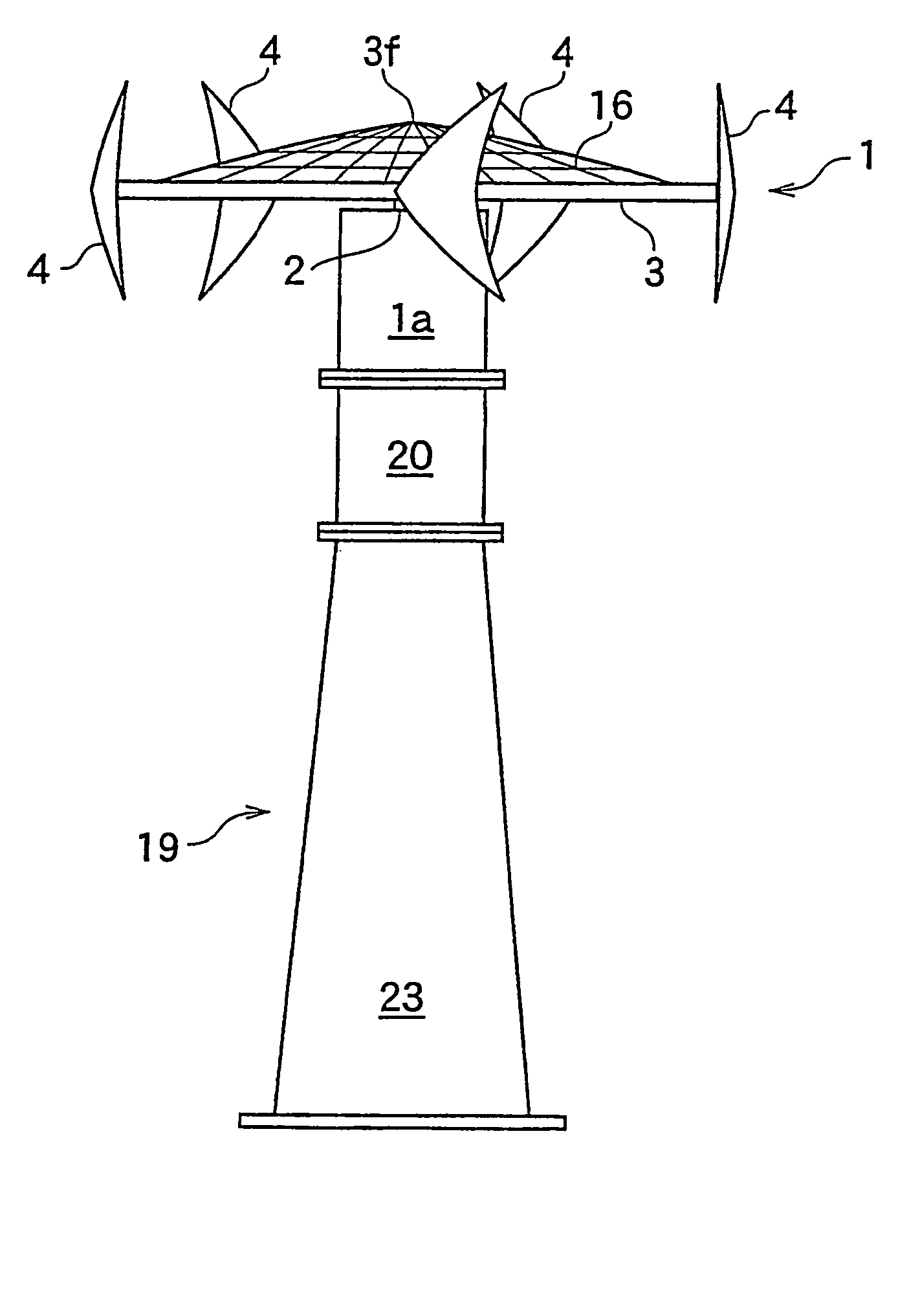
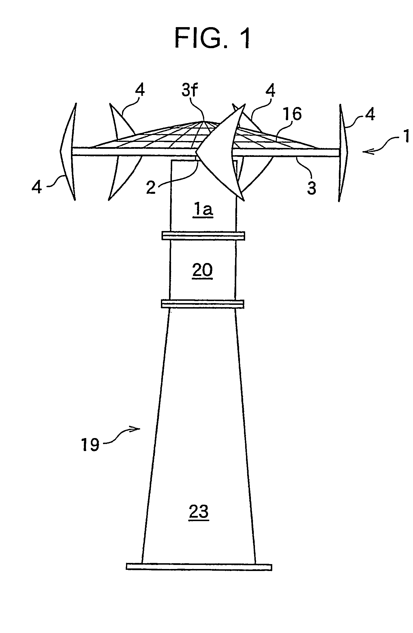
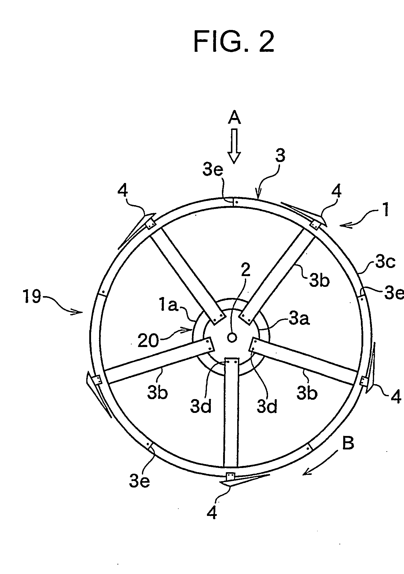
Wind power generator, windmill, and spindle and blade of the windmill
a wind power generator and windmill technology, applied in the direction of renewable energy generation, vessel construction, greenhouse gas reduction, etc., can solve the problems of not being profitable, windmills will not be rotatable, air pollution and radioactivity injuries, etc., to reduce costs and expand the selective range of installation places
- Summary
- Abstract
- Description
- Claims
- Application Information
AI Technical Summary
Benefits of technology
Problems solved by technology
Method used
Image
Examples
first embodiment
[0082]FIG. 5 shows a right side view of the wind-receiving blade 4 of the first embodiment, and FIG. 6 is a horizontal sectional view taken along the line VI-VI in FIG. 5. The wind-receiving blade 4 comprises a support 41 and a wind-receiving portion 42, and molded from a soft elastic fiber reinforced plastics (FRP) or resin. The wind-receiving portion 42 is almost like a triangle and has a support body 42 for supporting a wind-receiving film 42b. The support body 42 has a curved portion and the film 42b is integrally formed on the support body 42. To achieve uniform thickness, the film 42b may be vinylon cloth or sheet in which resin is formed over the cloth, Thus, when the rear part of the wind-receiving portion 42 is subjected to strong wind pressure during rotation of the rotor 3, it can be curved like a caudal fin. Soft elastic fiber reinforced resin that forms the wind-receiving blade 4 includes unsaturated polyester resin, vinyl ester resin, epoxy resin, urethane resin, epoxy...
third embodiment
[0100]FIG. 9 is a left side view of a wind-receiving blade, and FIG. 10 is a top plan view. The same numerals are allotted to the same members and description thereof is omitted.
[0101] In the third embodiment, the wind-receiving blade 4 comprises a mounting support 41 and a vertical wind-receiving portion 42, which comprises a vertical support bone 42a . and a rectangular wind-receiving film plate 42b supported by the support bone 42a. As shown in FIG. 10, the mounting support 41 has horizontally a reversed L-shaped section and has a U-shape sectioned fixing portion 41a at the end. The fixing portion 41a is mounted such that an end face 41b is in parallel with a tangential line “L” at the circumference of a rotor 3 of a windmill 1. The mounting support 21 is tapered and projected forwards by 50 cm and transversely by 70 cm. This is because the wind-receiving blade 4 far from the main vertical shaft 2 to strengthen leverage effect. Numeral 41c denotes a thread bore through which a bo...
fourth embodiment
[0114] However, the wind-receiving portion 42 rotates while the front end of the support bone 42a projects inwards. So with rotation, negative pressure is generated inside the front of the wind-receiving portion 42 to give rotation-driving force. With increase in rotation speed, the rear end of the wind-receiving film plate 42b rotates while it is pressed out. This is because inertia exceeds air resistance, FIG. 12 is a front view of a wind-receiving blade 4; FIG. 14 is a central horizontal sectional view in FIG. 12; and FIG. 14 is a top plan view which shows that the wind-receiving blade 4 in FIG. 12 is mounted over a rotor. The same numerals are allotted to the same members as those in the foregoing embodiments and description thereof is omitted.
[0115] A wind-receiving portion 42 in the fourth embodiment is characterized by comprising the structure opposite to that in the third embodiment.
[0116] As shown in FIG. 13, a support bone 42a is bent to form a lobe 42c for generating rot...
PUM
 Abstract
Description
Claims
Application Information
 - R&D
- Intellectual Property
- Life Sciences
- Materials
- Tech Scout
- Unparalleled Data Quality
- Higher Quality Content
- 60% Fewer Hallucinations
Browse by: Latest US Patents, China's latest patents, Technical Efficacy Thesaurus, Application Domain, Technology Topic, Popular Technical Reports.
© 2025 PatSnap. All rights reserved.Legal|Privacy policy|Modern Slavery Act Transparency Statement|Sitemap|About US| Contact US: help@patsnap.com


