Immediate post-extraction implant

a post-extraction and implant technology, applied in the field of dental implants, can solve the problems of large conical cavity, inability to self-tuck implants, and inability to achieve self-tucking implants, and achieve the effect of promoting adhesion between the implant and the surrounding bone and putting in service in a reasonably short period of tim

Inactive Publication Date: 2005-04-21
ASHMAN ARTHUR +1
View PDF18 Cites 16 Cited by
  • Summary
  • Abstract
  • Description
  • Claims
  • Application Information

AI Technical Summary

Benefits of technology

[0012] The present invention is directed to a dental implant that may be used at the site of a recent tooth extraction and can be put into service in a reasonably short period of time. This implant has a lower self-tapping portion and an upper portion covered with a sintered material that is osteopromotive and osteoretentive so to promote adhesion between the implant and the surrounding bone.

Problems solved by technology

When a tooth is extracted, it leaves behind a rather large conically-shaped cavity, which does not lend itself to the insertion of a cylindrical implant if an artificial tooth is to be substituted for the removed tooth.
However, this requires that the patient live with an edentulous area without a functional prosthesis for a long period of time.
As the slope of the conical shape of the extraction site cannot be predicted in advance, these implants cannot be made self tapping.
As a result, no pressure can be applied to these implants for a significant period of time, i.e., until existing bone has grown around the implant to anchor it in place.
In addition, as a self-tapping implant is not used, there may not be intimate contact between the implant and the new bone, so the implant may eventually fail, even if a significant amount of time is allowed to pass before an artificial tooth is mounted on the implant and it is put into use.

Method used


Image

  • Immediate post-extraction implant
  • Immediate post-extraction implant
  • Immediate post-extraction implant

Examples


Embodiment Construction

[0025] The design requirements for dental implants placed into immediate extraction sites differ significantly from the design of general implants used presently for placement in edentulous jawbones. Today all implants used in immediate extraction sites are either threaded, coated with a surface material or sintered. However, these implants do not provide the best design for immediate fresh extraction sites. Such immediate extraction sites require an implant designed specifically to address the morphology of the bony defect created during the extraction of a tooth.

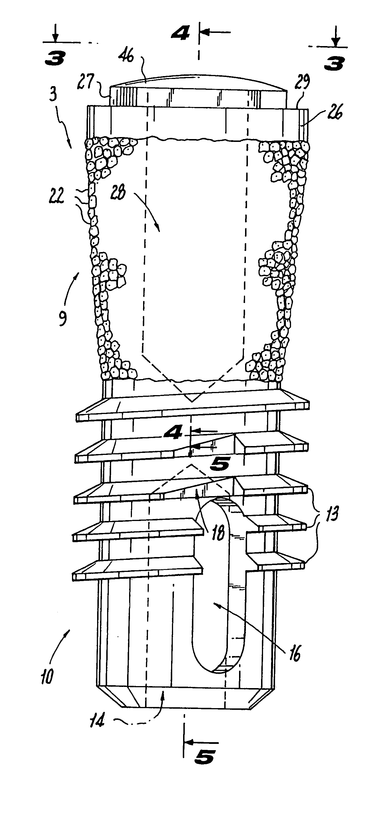
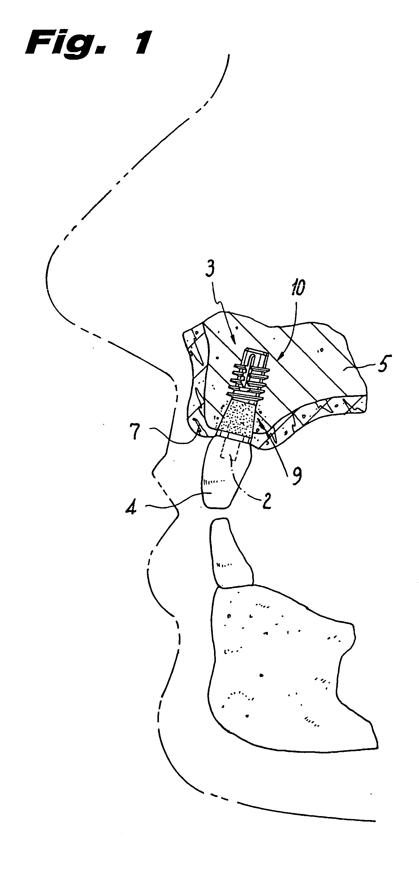
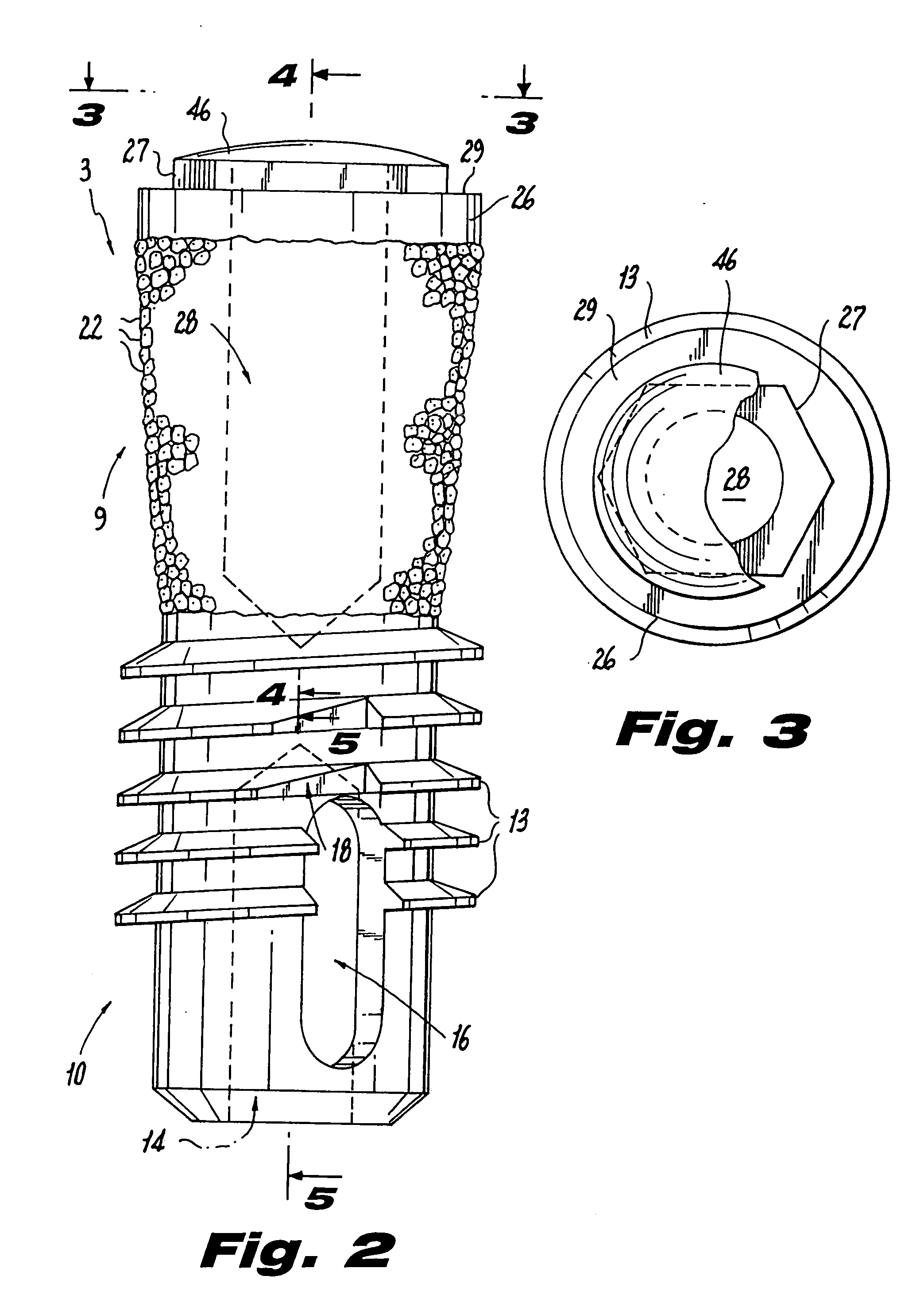
[0026] The implant system of the present invention is at least a two part screw-type dental implant 3 (FIG. 1), having a threaded cylindrical lower portion 10 that is buried in the bone 5 of the patient and an upper portion 9, preferably generally conically-shaped, that is attached thereto. The upper portion 9 is covered by soft tissue 7. A post or abutment 2 is shown in dotted line extending from upper portion 9 and supp...


PUM


Abstract

A submergible or non-submergible (“one stage”) screw-type implant for use in the immediate post-extraction site of a patient's tooth. In order to increase the ability of regenerated bone to anchor the implant, an upper portion of the implant has a preferably generally conical shape and has a plurality of spherical projections sintered to its outer surface to make it suitable for bone integration and retention. The lower portion of the implant has a cylindrical shape with threads extending over a portion thereof. A channel is located through the threads and is shaped so that one side forms a cutting edge that makes the lower portion of the implant self-tapping into the bone at the base of the tooth extension socket.

Description

[0001] This is a continuation of U.S. application Ser. No. 10 / 183,731, filed Jun. 25, 2002, now pending, which is a continuation of U.S. application Ser. No. 09 / 248,079, filed Feb. 10, 1999, now U.S. Pat. No. 6,413,089, issued Jul. 2, 2002. Each of these prior applications is incorporated by reference herein in its entirety.TECHNICAL FIELD [0002] This invention relates generally to dental implants, and, more particularly, to submergible screw-type implants. BACKGROUND ART [0003] Screw-type implants are well known in the art. U.S. Pat. No. 3,499,222 of L. I. Linkow et al. (the “'222 patent”) discloses screw-type implants that may be buried in the alveolar ridge crest bone of a patient in an edentulous region. The implant has a threaded lower portion that may be screwed into an opening created in the bone after the tissue has been displaced. A coronal portion protrudes above the bone and is used to support an artificial dental appliance, e.g., an artificial tooth or bridge. [0004] Mor...

Claims


Application Information

Patent Timeline
Patent Type & Authority Applications(United States)
IPC IPC(8): A61C8/00
CPCA61C8/0006A61C8/008A61C8/0039A61C8/0022
Inventor ASHMAN, ARTHURLINKOW, LEONARD
Owner ASHMAN ARTHUR
Why Eureka
Try Eureka