Intraocular implant and an artificial lens device

a technology of intraocular implants and artificial lenses, applied in the field of intraocular implants and artificial lens devices, can solve the problems of poor performance of implants, inability to restore any faculty of accommodation to operated patients, and practically non-existent accommodation, so as to optimize the ability of the subject to accommoda

Inactive Publication Date: 2005-04-21
HUMANOPTICS AG
View PDF1 Cites 121 Cited by
  • Summary
  • Abstract
  • Description
  • Claims
  • Application Information

AI Technical Summary

Benefits of technology

[0029] By computer-assisted design methods, it is possible with given mechanical characteristics (i.e. given materials) to determine the various critical dimensions and shapes for the implant and for the gutter, particularly concerning the hinges of the haptic arms of the implant and concerning

Problems solved by technology

Until now, the implants used have not had the ability to restore any faculty of accommodation to an operated patient.
It would appear that that implant provides poor performance since the mechanism for compressing the case produces only a very small amount of movement in the optical portion, so the faculty of accommodation is practically non-existent.
In that device, the fibrosis tissue whose growth is encouraged i

Method used


Image

  • Intraocular implant and an artificial lens device
  • Intraocular implant and an artificial lens device
  • Intraocular implant and an artificial lens device

Examples


first embodiment

[0063] The device of the invention also comprises an element that is separate from the implant and that is shown in a rest state in FIGS. 8 and 10, for a first embodiment, and in FIG. 9 for another embodiment. This element 120 carries a gutter-shaped portion 121 defined by an anterior lip 122 and a posterior lip 123 provided with an internal bead 124, the posterior lip 123 being extended as a dome 125 closing the posterior portion of this element 120. This gutter-shaped portion is provided with transverse slots 126 co-operating with its deformation ability both in the direction parallel to its axis of revolution R and in a direction perpendicular thereto.

[0064] The greatest diameter of the element 120, referenced d in FIG. 10 and referred to as its equatorial diameter, is substantially equal, at rest, to the diameter of the lens of a subject, and in particular the diameter which the lens used to have when the subject who is to be operated on was 25 to 30 years old, and as measured i...

embodiment 140

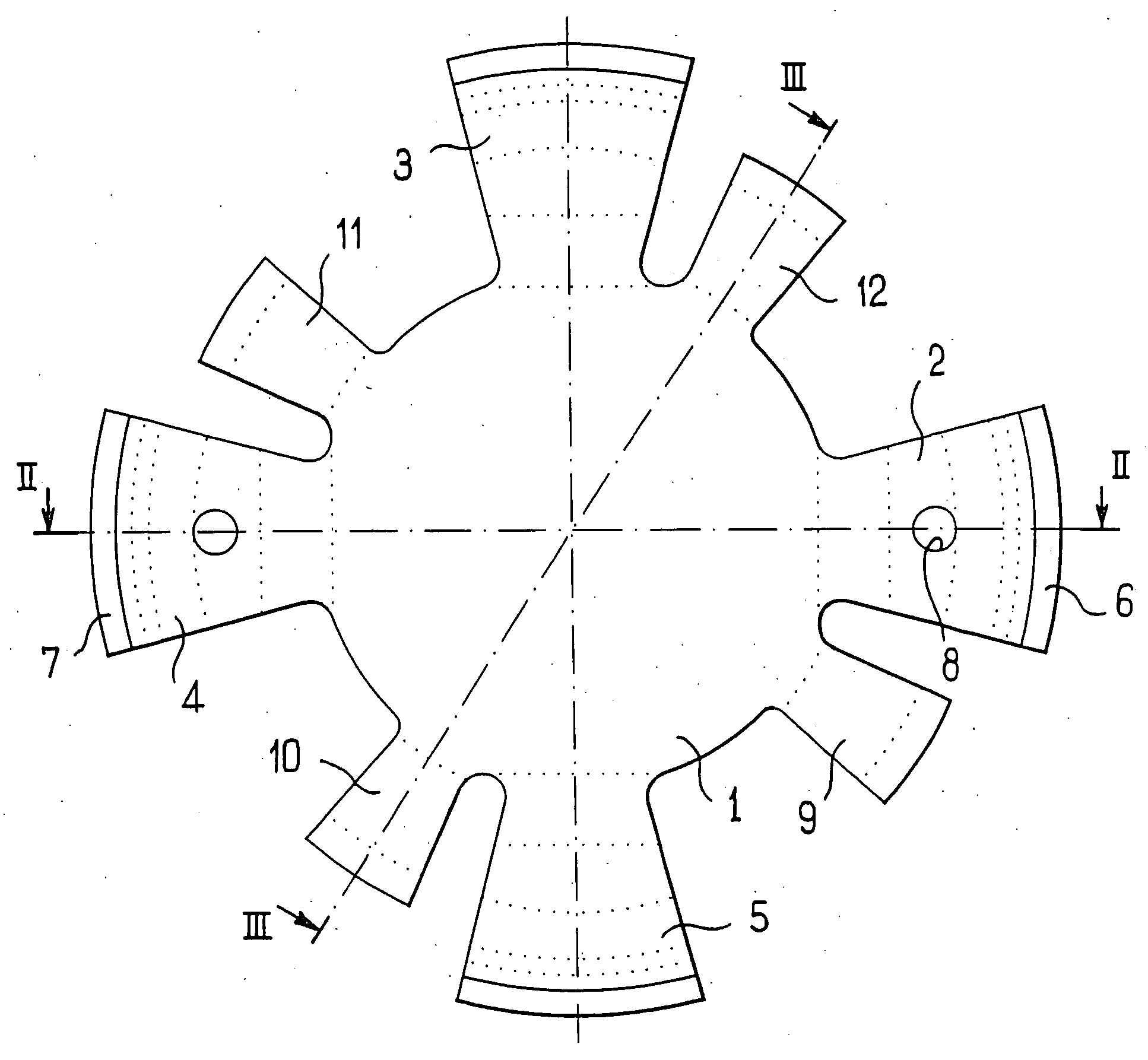
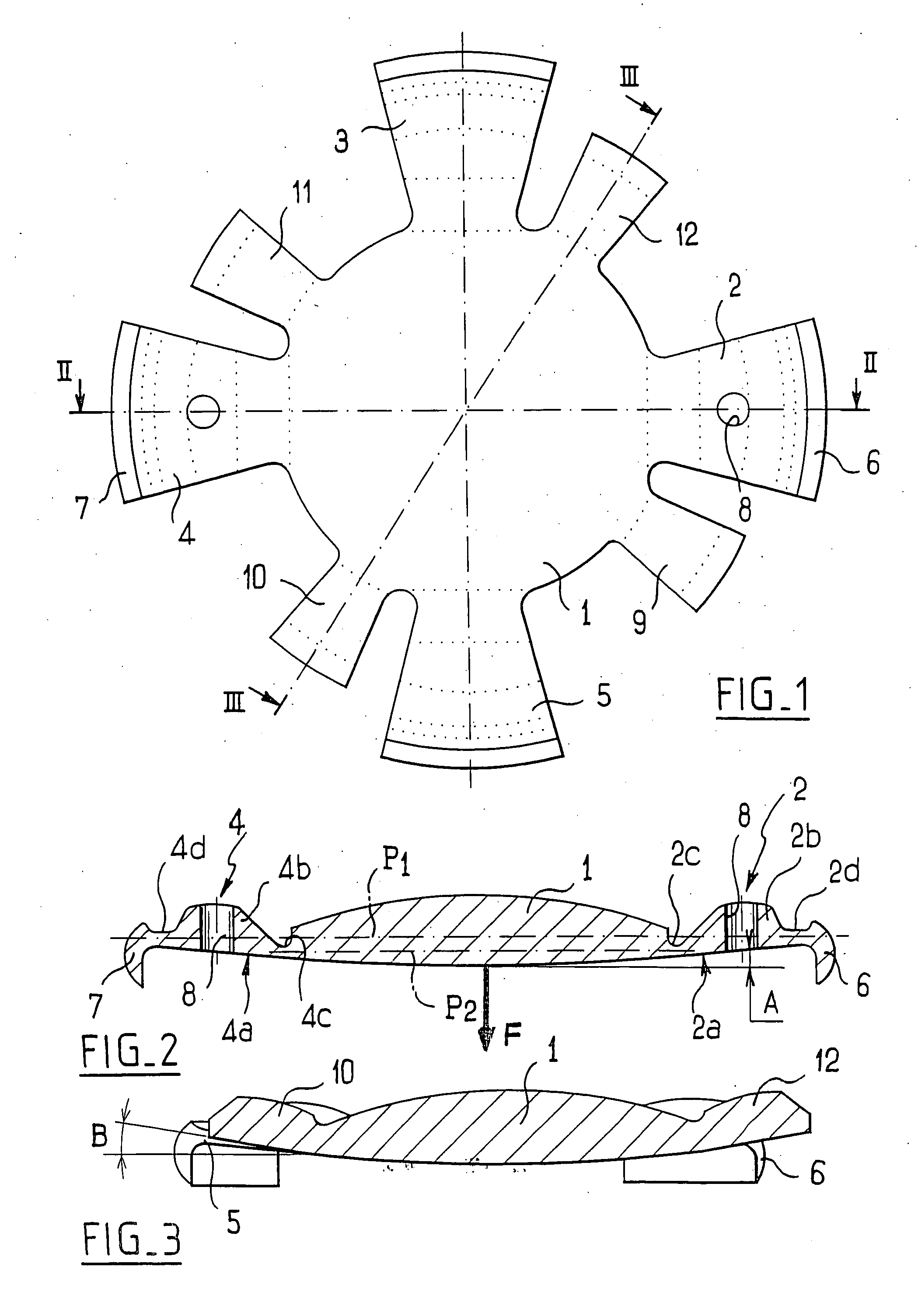
[0067]FIG. 14 is a plan view of a variant embodiment 140 of the implant 100 of FIG. 7. The difference between the two embodiments lies in the fact that in FIG. 14, the implant 140 has six haptic arms 141 separated from one another by gaps 142 that are keyhole-shaped. As in FIG. 7, these arms are connected to the central lens 143 by hinge zones 144 and to respective end shoes 145 likewise by hinge zones that are not visible in FIG. 14.

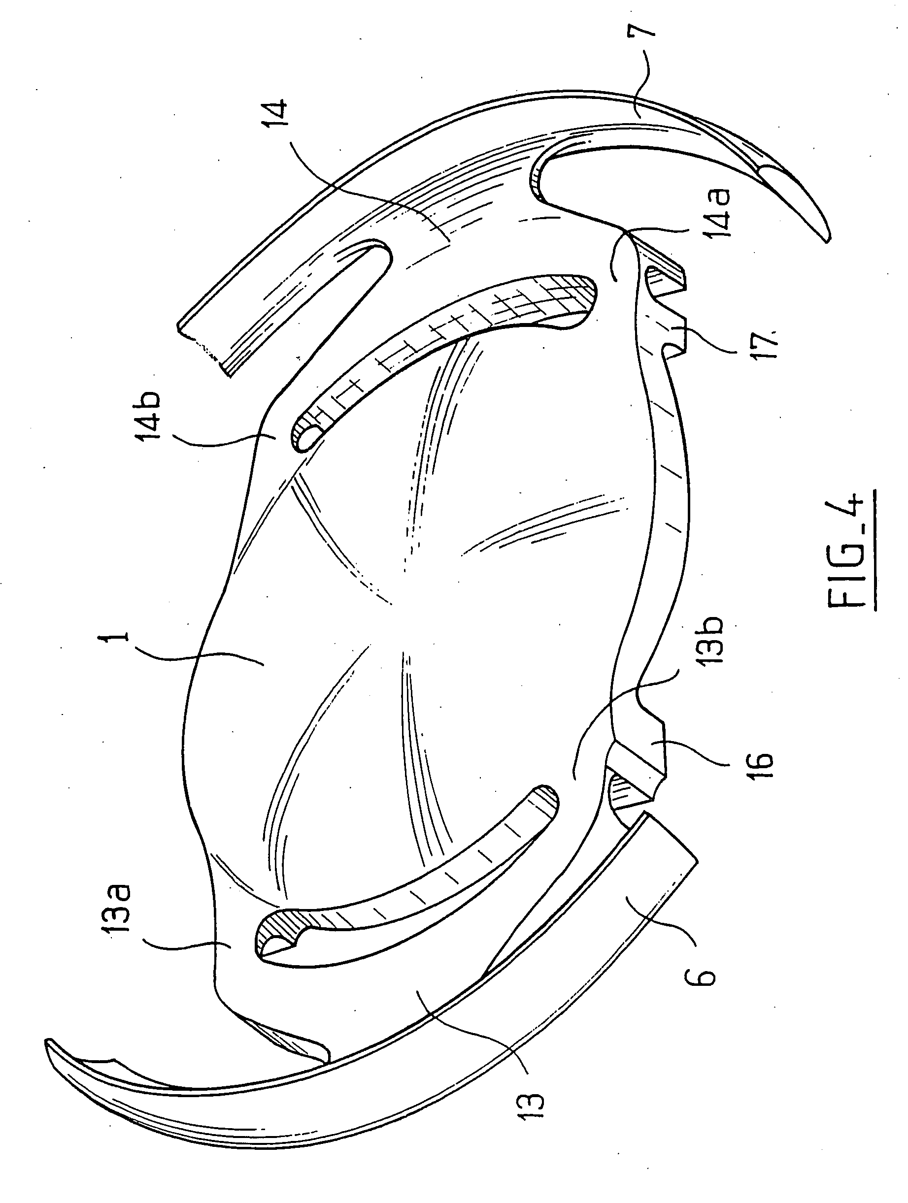
[0068]FIGS. 15 and 17 show the artificial lens device of the invention in its equilibrium state when the implant 100 is received in the case example 120, 130. The implant bears against the inside surface of the gutter by means of the substantially toroidal outside surfaces of the shoes which thus press closely against said inside surface. The implant exerts a force on the case element which tends to expand radially. However, the case element opposes this force with force that leads to a rest state in which the implant is much more highly deformed than i...


PUM


Abstract

An accommodating intraocular implant for locating in the capsular bag, the implant comprising a single piece of elastically deformable material constituting a central lens (1) and at least two haptic portions (2, 4) in the form of radial arms for bearing via their free ends against the equatorial zone of the capsular bag, the free end of each radial arm (2, 4) being fitted with a shoe (6, 7) of substantially toroidal outside surface enabling the implant to bear against the equatorial zone of the bag, the connection between each shoe (6, 7) and the corresponding arm (2, 4) being of the hinge type situated in the vicinity of the posterior edge of the shoe (6, 7) and being formed by a first thin portion (2d, 4d) of the arm, while the connection between each arm and the lens is of the hinge type implemented at the anterior surface of the lens by a second likewise thin portion (2c, 4c) of the arm, the plane (P1) containing the first thin portions being situated behind the plane (P2) containing the second thin portions.

Description

CROSS REFERENCE TO RELATED APPLICATION [0001] This application is a continuation-in-part of co-pending application Ser. No. 10 / 691,962, filed on Oct. 24, 2003, which is a division of Ser. No. 09 / 958,943, filed Oct. 16, 2001. Application Ser. No. 10 / 691,962 is the national phase of PCT International Application No. PCT / FR01 / 00407 filed on Feb. 13, 2001 under 35 U.S.C. § 371. The entire contents of each of the above-identified applications are hereby incorporated by reference.[0002] The present invention relates to the field of intraocular implants, and more precisely to the field of lenses that are implanted after cataract surgery consisting in removing the natural lens from the capsular bag through a central and anterior capsulotomy (capsulorexis) having a diameter of 5 millimeters (mm) to 6 mm. As a result, the posterior and equatorial portions of the capsular bag are preserved. BACKGROUND OF THE INVENTION [0003] Replacing the natural lens with an implant has become an operation th...

Claims


Application Information

Patent Timeline
IPC IPC(8): A61F2/16
CPCA61F2/1613A61F2/1629A61F2210/0014A61F2/1694A61F2/1648
Inventor HANNA, KHALIL
Owner HUMANOPTICS AG
Why Eureka
Try Eureka