Shaped filler for implantation into a bone void and methods of manufacture and use thereof

a technology of shaped fillers and bone voids, which is applied in the direction of joint implants, manufacturing tools, prostheses, etc., can solve the problems of bone bleeding, acute, idiopathic or chronic pain to the patient, and both putty-like materials and loose granular materials have the potential to migrate after surgery

Inactive Publication Date: 2005-04-21
THERICS
View PDF99 Cites 35 Cited by
  • Summary
  • Abstract
  • Description
  • Claims
  • Application Information

AI Technical Summary

Problems solved by technology

However, both putty-like materials and loose granular materials have the potential to migrate after surgery.
Filler pieces and materials which are in current use for filling bone donor sites have often not resulted in ingrown bone of the same quality as the removed bone, sometimes resulting in adhesions between regrown bone and healed adjacent soft tissue, with resulting acute, idiopathic or chronic pain to the patient.
Where the bone void filler is autograft, current surgical techniques for harvesting bone for autografts results in bone bleeding to an extent that the bleeding sometimes obscures observation of the site of the cut and hinders fitting of the filler piece to the bone void.
However, if the surface of a filler piece is cut and shaped to fit during surgery, detailed surface patterns from the original manufacture might be removed during cutting and shaping and therefore may not remain after cutting and shaping.

Method used


Image

  • Shaped filler for implantation into a bone void and methods of manufacture and use thereof
  • Shaped filler for implantation into a bone void and methods of manufacture and use thereof
  • Shaped filler for implantation into a bone void and methods of manufacture and use thereof

Examples


Embodiment Construction

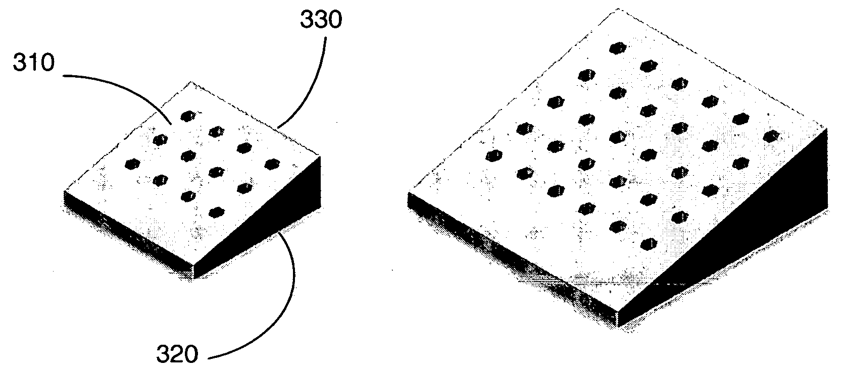
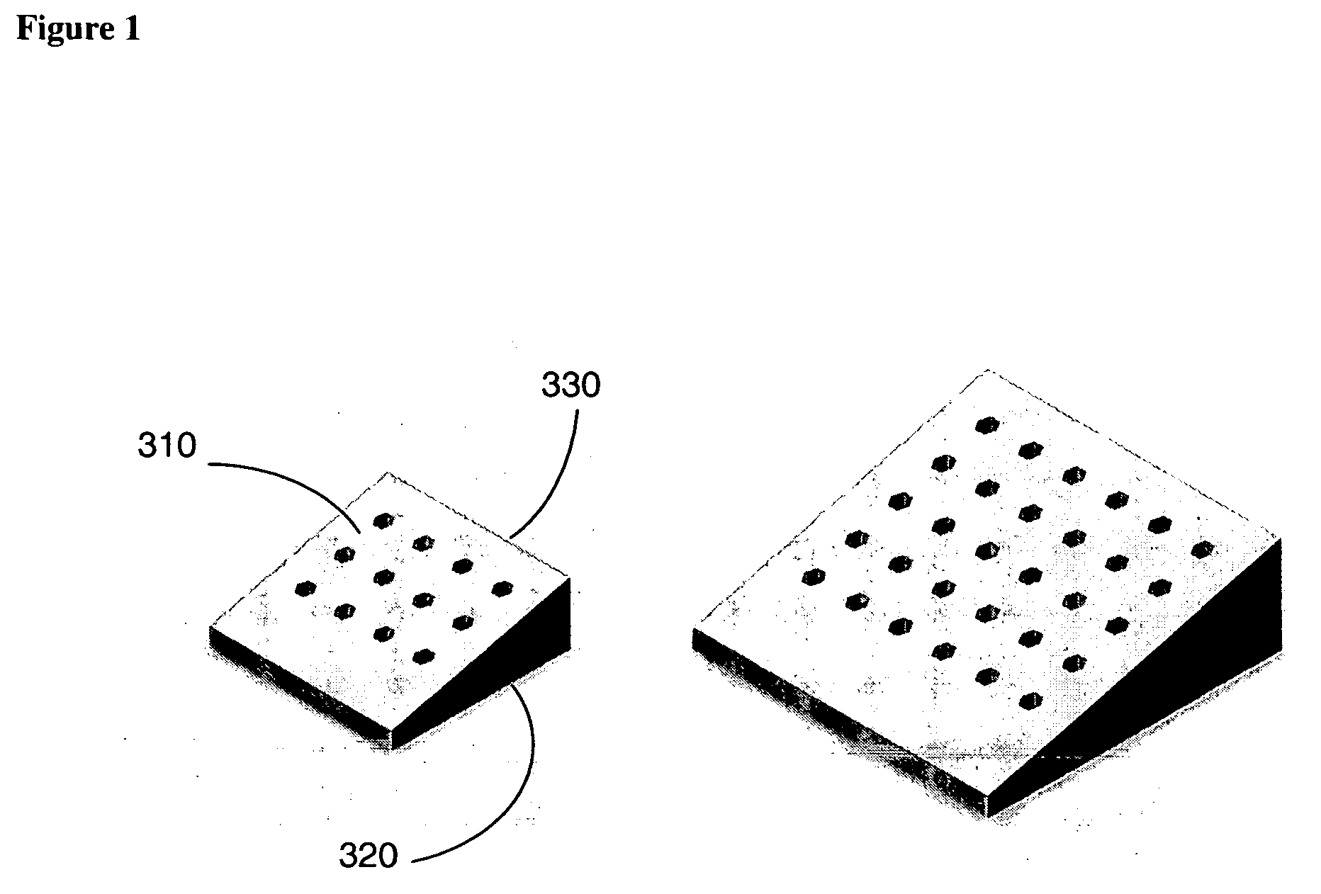
[0023] The invention includes bone void filler pieces of shapes suitable for implantation in a bone void that was surgically created, or otherwise resulting from other conditions such as disease or traumatic injury. The filler pieces may be suitable for use in a void in the crest of the ileum, which may be used as a bone donor site.

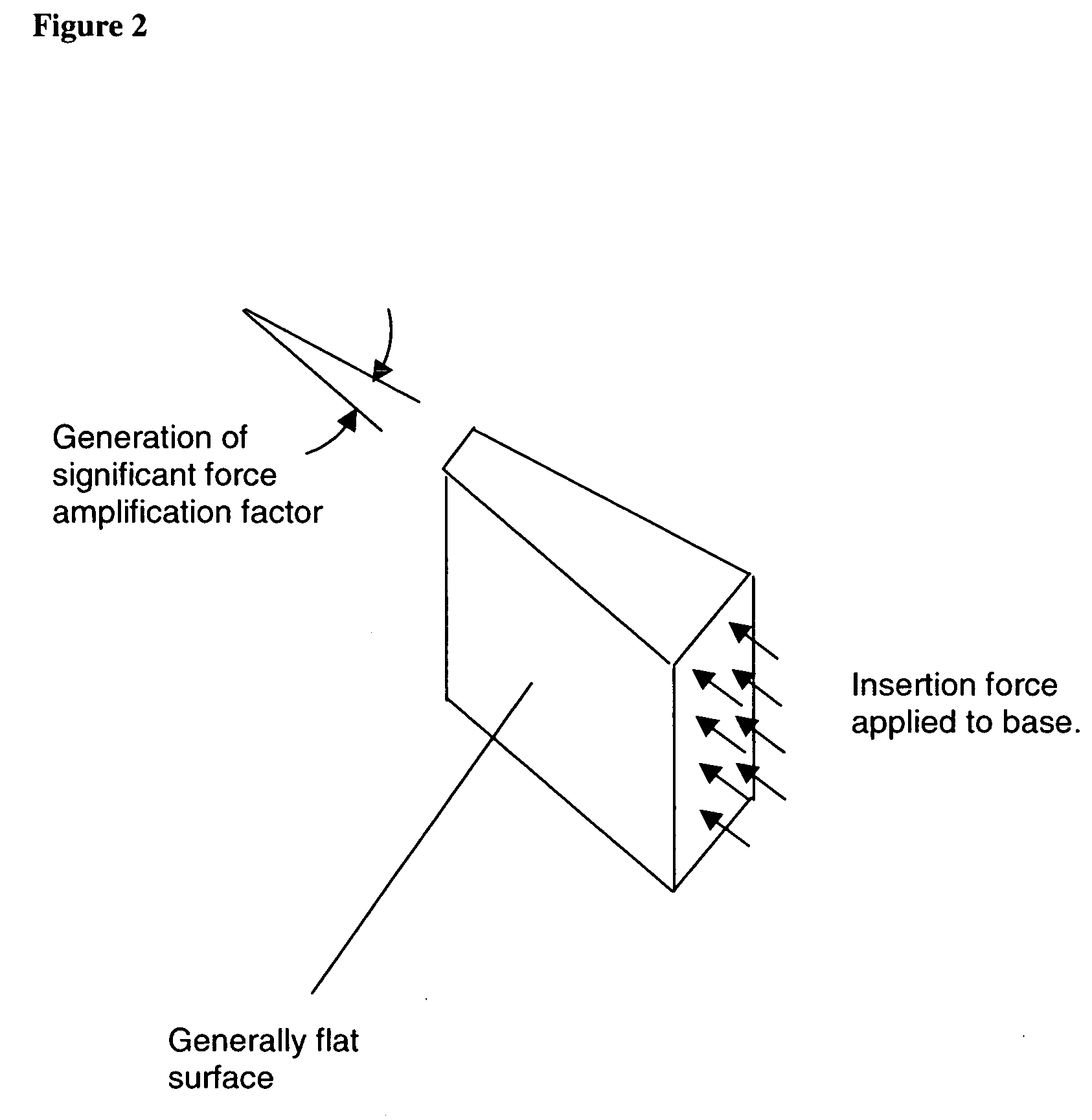
[0024] In one embodiment of the invention, the shape of the filler piece may be a shape that is substantially a wedge or a truncated wedge. The wedge or truncated wedge may be defined by a first generally flat surface and a second generally flat surface that is angled with respect to the first generally flat surface. The two surfaces may be angled with respect to each other by an angle of about 15 degrees of less, or more generally, an angle of less than about 30 degrees. The filler piece may also comprise a base surface connecting the two generally flat surfaces at the larger end of the filler piece. FIG. 1 shows the shape of the filler piece as being p...


PUM

PropertyMeasurementUnit
angleaaaaaaaaaa
pore sizeaaaaaaaaaa
pore size distributionaaaaaaaaaa

Abstract

The invention is directed to shaped bone void filler pieces having defined porosity. In embodiments of the invention, the shaped bone void filler pieces are presented substantially as wedges, wafers, and axisymmetric bone void filler pieces. The bone void filler pieces further comprise surface and internal features such as recesses, channels, and/or voids. The bone void filler pieces optionally comprise demineralized bone matrix. The invention further is directed to methods of making and methods of using the bone void filler pieces. In another embodiment of the invention, the bone void filler pieces are produced using three dimensional printing methods. In yet another embodiment of the invention, the bone void filler pieces are manufactured with selected porogens integrated therein, which optionally are decomposed following production through a heat-mediated decomposition process, resulting in voids in the bone void filler spaces previously occupied by the porogen(s).

Description

CROSS-REFERENCE TO RELATED APPLICATIONS [0001] This application claims the benefit of U.S. Provisional Application No. 60 / 512,498, filed Oct. 17, 2003; U.S. Provisional Application No. 60 / 512,414, filed Oct. 17, 2003; and U.S. Provisional Application No. 60 / 577,736, filed Jun. 7, 2004, the disclosures of each of which are herein incorporated by reference in their entireties.BACKGROUND OF THE INVENTION [0002] Voids are surgically created in bones for a variety of reasons, including donation of bone for use at another site, treatment of cancer or bone necrosis, and repair of traumatic injury or congenital conditions. The materials known to be used for filler in bone voids include collagen, allograft, bone chips obtained from the patient during surgery, demineralized bone matrix, and ceramic materials in the form of granules. Ceramic materials are of interest at least because of their ready availability and the avoidance of possible disease transmission to the patient. Members of the c...

Claims


Application Information

Patent Timeline
Patent Type & Authority Applications(United States)
IPC IPC(8): A61F2/00A61F2/28A61F2/30A61L27/12A61L27/42A61L27/56
CPCA61F2/28A61L2430/02A61F2002/3008A61F2002/30153A61F2002/30158A61F2002/3021A61F2002/30224A61F2002/30225A61F2002/30266A61F2002/30785A61F2002/30787A61F2002/30789A61F2002/30968A61F2002/30985A61F2230/0019A61F2230/0026A61F2230/0067A61F2230/0069A61F2230/0082A61F2250/0023A61F2250/0098A61F2310/00293A61L27/12A61L27/3608A61L27/365A61L27/425A61L27/56A61F2002/30011B33Y80/00
Inventor SHAPPLEY, BEN R.BRADBURY, THOMAS J.MATERNA, PETER A.PRYOR, TIMOTHY J.BLUM, JOHNRECBER, ALI CEM
Owner THERICS
Why Eureka
Try Eureka