Transducer, electronic equipment, and method of adjusting frequency of transducer

a transducer and electronic equipment technology, applied in the field of transducers, can solve the problems of difficult accurate detection of the rotation of the transducer, leakage of the base member, impaired oscillation, etc., and achieve the effect of increasing the adjustment mass, improving the process yield of the transducer, and increasing the frequency range of the adjustable rang

Inactive Publication Date: 2005-04-28
SEIKO EPSON CORP
View PDF6 Cites 6 Cited by
  • Summary
  • Abstract
  • Description
  • Claims
  • Application Information

AI Technical Summary

Benefits of technology

[0033] In this manner, since the distal end of the second extending portion is formed larger than the proximal end thereof, the amount of adjustment of the mass can be increased, and the adjustable range of the frequency can be increased correspondingly. Therefore, failure of adjusting the frequency can be avoided and hence the process yield of the transducer can be improved.

Problems solved by technology

However, in the transducers described above, there is a problem that oscillation of the arm member may concentrate at the single supporting member provided at the center of the base portion and hence leak to the base member.
This caused impaired oscillation.
As a result, accurate detection of the rotation of the transducer is difficult.
Also, torsional oscillation cannot be detected with a high degree of accuracy since the angular speed is detected by the supporting member located apart from the oscillating strip.
Furthermore, according to the method of adjusting frequency in the related art, even when an attempt was made to adjust the difference between the frequency of the driving oscillation and the frequency of the detected frequency within a predetermined range, there might be a case in which the frequency could not be sufficiently adjusted.
This results in lowered process yield because the adjusting range is small.
In addition, the frequency of the driving oscillation and the frequency of the detected oscillation may be subject to affects with respect to each other.

Method used


Image

  • Transducer, electronic equipment, and method of adjusting frequency of transducer
  • Transducer, electronic equipment, and method of adjusting frequency of transducer
  • Transducer, electronic equipment, and method of adjusting frequency of transducer

Examples


exemplary embodiment 1

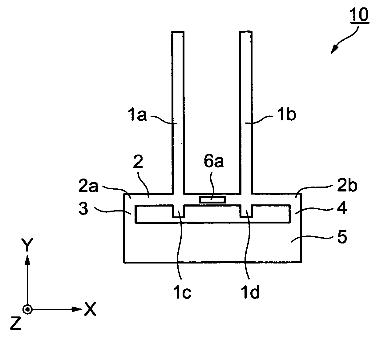
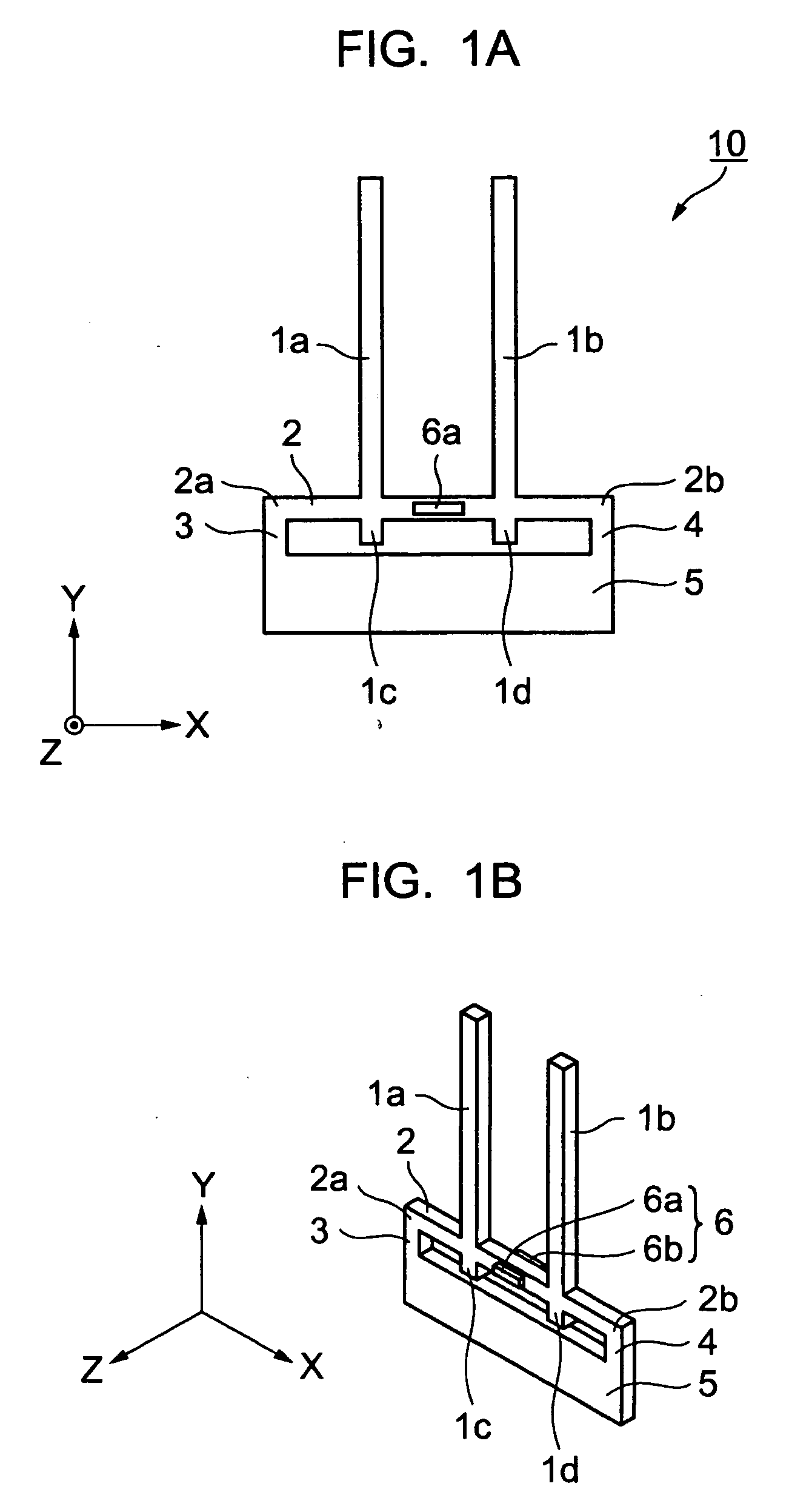
[0054]FIG. 1A and FIG. 1B are schematics showing a structure of a transducer according to a first exemplary embodiment. A transducer 10 according to the first exemplary embodiment generates oscillation to generate a Coriolis force corresponding to the rotation about the Y-axis (hereinafter “driving oscillation”) and oscillation to detect the rotation caused by the Coriolis force (hereinafter “detecting oscillation”). The transducer 10 generates the driving oscillation when in drive mode generates the detecting oscillation in detecting mode. In order to generate oscillation in both modes described above, the transducer 10 includes a pair of oscillating reeds 1a, 1b, a beam 2, a first connecting device (connecting member) 3, a second connecting device (connecting member) 4, a base member 5, and a detecting unit 6.

[0055] The pair of oscillating reeds 1a, 1b are rod-shaped members formed of crystal extending along the Y-axis in parallel to each other and having a predetermined length. ...

second exemplary embodiment

[0076]FIG. 5A, FIG. 5B, and FIG. 5C are schematics showing the structure of a transducer according to the second exemplary embodiment. A transducer 20 according to the second embodiment includes the pair of oscillating reeds 1a, 1b, the beam 2, the first connecting device 3, the second connecting device 4, the base member 5, and the detecting unit 6, as in the transducer 10 of the first exemplary embodiment, and a detecting unit 7, which is provided at a different point from the transducer 10 of the first exemplary embodiment. The detecting unit 7 includes detecting electrodes 7a, 7b having the same structure as the detecting electrodes 6a, 6b of the transducer 10 in the first exemplary embodiment.

[0077] The detecting units 6, 7 are provided at the point other than the portion between the pair of oscillating reeds 1a, 1b of the beam 2, and, specifically, the detecting unit 6 is provided between one end 2a of the beam 2 and the one oscillating reed 1a, and the detecting unit 7 is pr...

third exemplary embodiment

[0080]FIG. 6A and FIG. 6B are schematics showing the structure of a transducer according to the third exemplary embodiment, respectively. A transducer 30 in the third embodiment includes the pair of oscillating reeds 1a, 1b, the beam 2, the first connecting device 3, the second connecting device 4, the base member 5, and the detecting unit 6 as in the case of the transducer 10 of the first exemplary embodiment. The transducer 30 includes a third connecting device (connecting member) 8, which is different from the transducer 10.

[0081] The third connecting device 8 is a rod-shaped member formed of crystal extending in the Y-axis direction and having a predetermined length to connect the substantially center portion of the beam and the base member 5. Here, the distance d1 between one oscillating reed 1a and the third connecting device 8 and the distance d2 between the other oscillating reed 1b and the third connecting device 8 are set to values shorter than the distance d3 between one...


PUM


Abstract

To provide a transducer that can detect the rotation of the transducer with high degree of accuracy, a transducer includes a pair of oscillating reeds extending in the Y-direction to generate a first oscillation to generate a Coriolis force corresponding to the rotation of the transducer, a beam extending in the X-direction and connected to the pair of oscillating reeds, a first detecting unit provided on the beam to detect deformation of the beam due to a second oscillation of the pair of oscillating reeds caused by the Coriolis force, a base member to support the beam, a first connecting device to connect one end of the beam and the base member, and a second connecting device to connect the other end of the beam and the base member.

Description

BACKGROUND OF THE INVENTION [0001] 1. Field of Invention [0002] Exemplary aspects of the present invention relate to a transducer, such as a gyroscope, electronic equipment provided with the transducer, and a method of adjusting the frequency of the transducer. [0003] 2. Description of Related Art [0004] Japanese Examined Patent Application Publication No. 7-69180 discloses a transducer including a base portion connected to an arm member to generate oscillation corresponding to the rotation of the transducer. The base portion is fixed to a base member via a supporting member provided to project from the center of the base portion therefrom. The supporting member detects torsional oscillation, to detect the rotation of the transducer. [0005] Japanese Unexamined Patent Application Publication No. 10-160479 discloses a method of adjusting frequency of a transducer by changing the mass of the respective oscillating strips by adding a mass to the distal end of one of an oscillating strip...

Claims


Application Information

Patent Timeline
Patent Type & Authority Applications(United States)
IPC IPC(8): G01C19/56G01C19/5628G01F25/00G01P21/00
CPCG01C19/56
Inventor EGUCHI, MAKOTOKANNA, SHIGEO
Owner SEIKO EPSON CORP
Why Eureka
Try Eureka