
Cushioned steering for articulated vehicle

Active Publication Date: 2005-04-28
CNH IND AMERICA LLC +1
View PDF7 Cites 19 Cited by
  • Summary
  • Abstract
  • Description
  • Claims
  • Application Information

AI Technical Summary

Benefits of technology

[0008] The work vehicle also has a variable displacement pump that responds to the deceleration by reducing the displacement of the pump.

Problems solved by technology

As one might expect, these repeated and extreme turns place a significant strain on an articulated vehicle as the steering cylinders reach the end of their travel and the front and rear frames of the vehicle bang against each other.

Method used


Image

  • Cushioned steering for articulated vehicle
  • Cushioned steering for articulated vehicle
  • Cushioned steering for articulated vehicle

Examples


Embodiment Construction

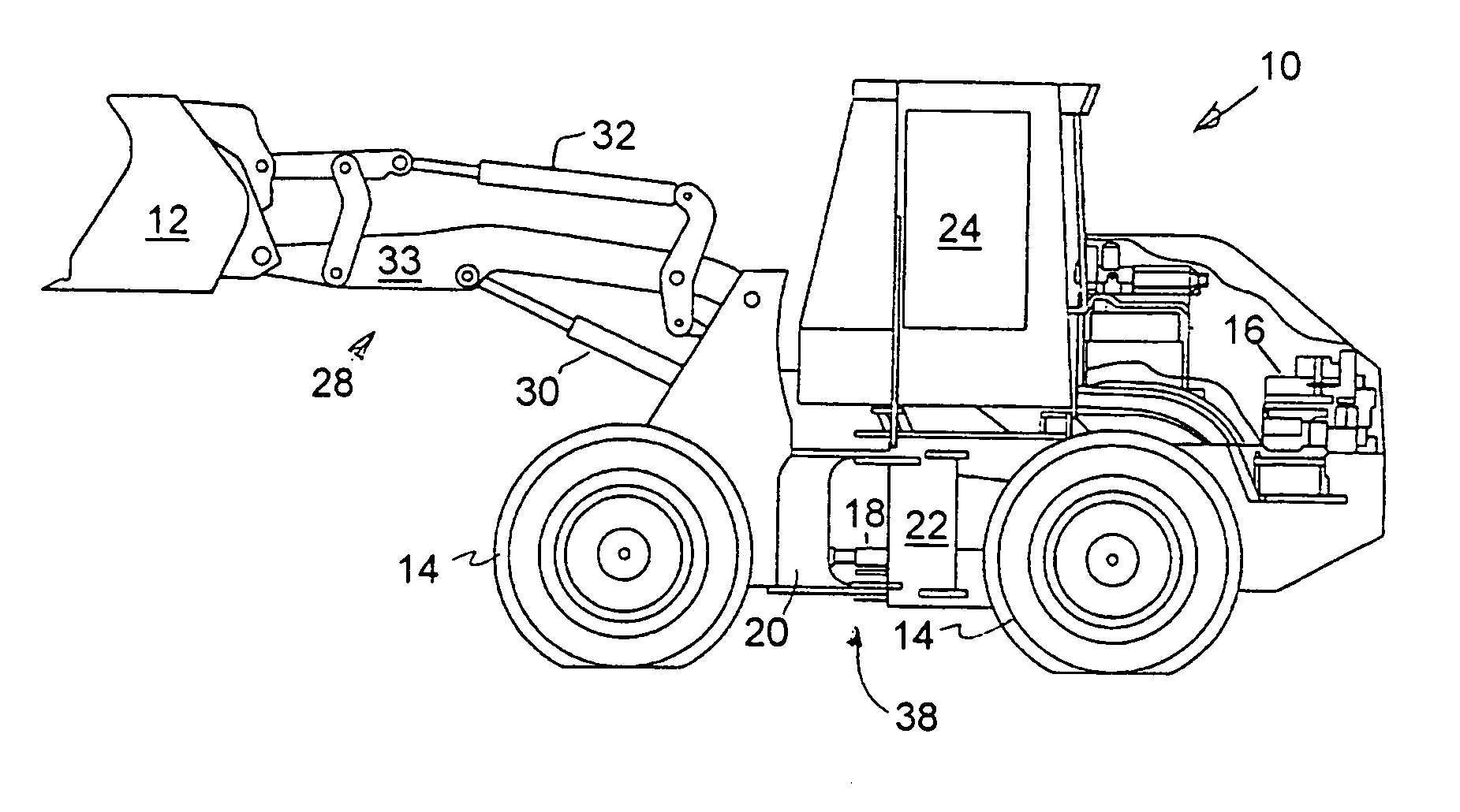
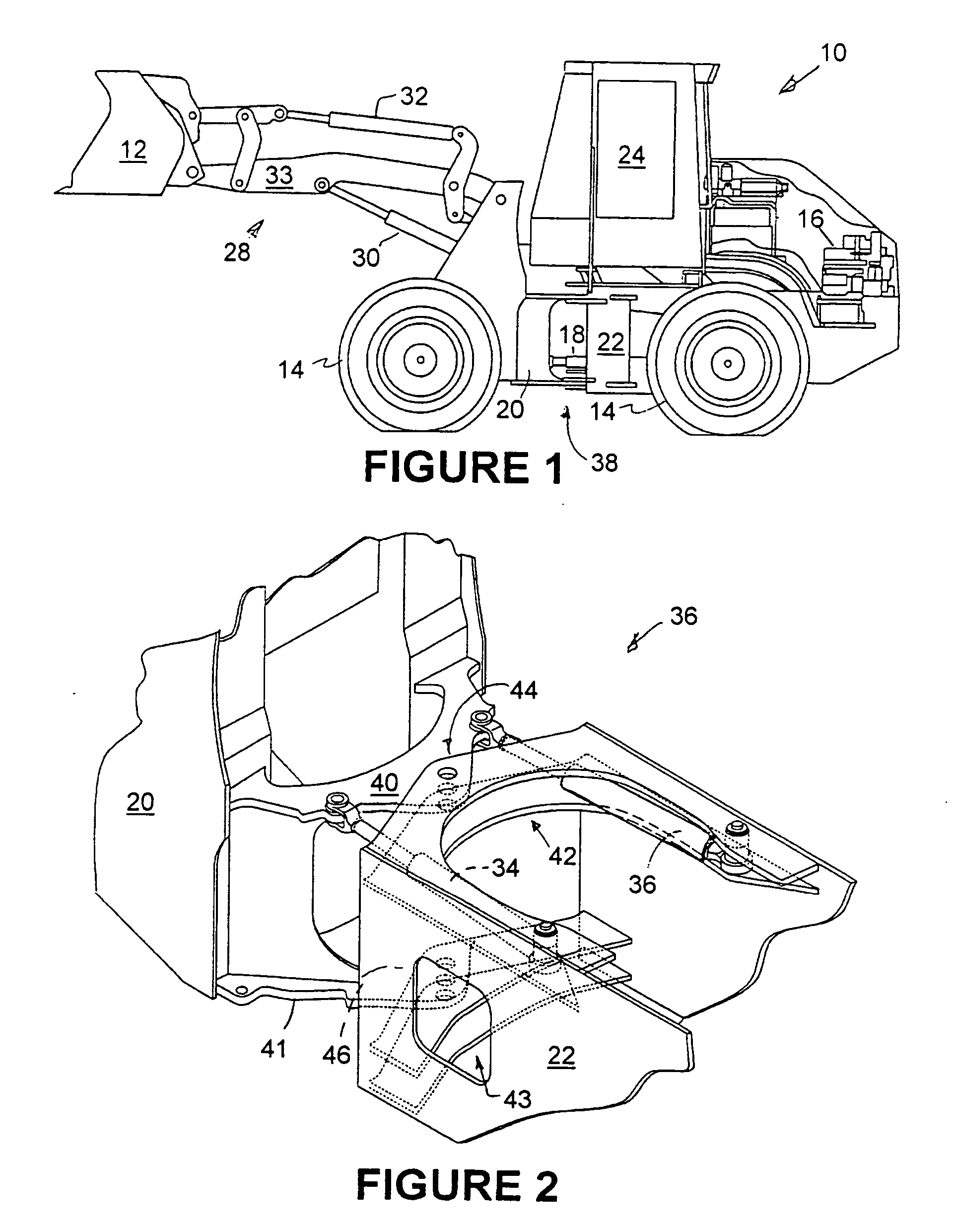
[0020]FIG. 1 illustrates a side view of an articulated work vehicle, such as a wheel loader 10 with a work implement, such as a bucket 12 in a partially lifted position.

[0021] Wheel loader 10 includes four wheels 14 of which the left two wheels are shown in FIG. 1. The left two wheels support the vehicle on the left hand side. Two identical wheels are similarly arranged in a fore-and-aft relation and extend from the right hand side of the vehicle. All four wheels are driven by engine 16 and support the vehicle as it travels over the ground.

[0022] The driveshaft 18 extends between a front frame 20 and rear frame 22. The driveshaft 18 transmits power from engine 16 to the front wheels of the vehicle which are mounted on the front frame 20. The engine also drives the rear wheels of the vehicle which are mounted on the rear frame 22. A transmission (not shown) is coupled between the engine and the wheels to provide for multiple gear reductions.

[0023] An operator's compartment or cab ...


PUM


Abstract

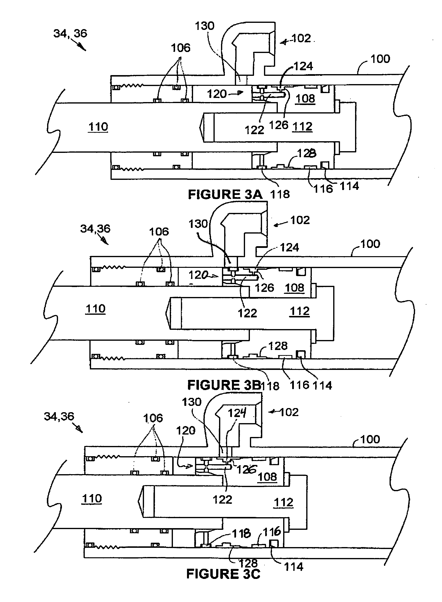
An articulated wheel loader provides a cushioned deceleration at the limits of its turning to the left and to the right by reducing fluid flow through a hydraulic steering cylinder as the articulated frames approach abutment. The throttled fluid flow causes a variable displacement pump to de-stroke, which further cushions the deceleration.

Description

FIELD OF THE INVENTION [0001] The invention relates generally to construction vehicles. More particularly it relates to articulated construction vehicles, such as wheel loaders. BACKGROUND OF THE INVENTION [0002] Wheel loaders are generally vehicles with a work implement such as a loader or bucket on the front that can be raised and lowered to scoop up, carry and drop particulate material. They are called “wheel” loaders since they are supported on large steerable wheels. Many wheel loaders are articulated vehicles that steer by “bending” the frame and not by turning the wheels, front and / or rear, with respect to the frame. Articulated wheel loaders do not have a single frame to which the front and rear wheels are mounted, but have at least two sub-frames that are coupled together to pivot or articulate with respect to each other about a generally vertical axis. Hydraulic steering cylinders are positioned between the sub-frames to extend and retract to bend the articulated vehicle. ...

Claims


Application Information

Patent Timeline
IPC IPC(8): B62D5/06B62D5/093B62D5/12B62D12/00B62D53/02
CPCB62D5/061B62D5/093B62D53/021B62D12/00B62D5/12
Inventor HENNEMANN, MATTHEW J.NATZKE, DAVID R.DUNN, DONNELL L.MICKELSON, ROGER D.
Owner CNH IND AMERICA LLC
Learn More