Valve for controlling a fluid

a valve and fluid technology, applied in the direction of valve details, valve arrangement, operating means/releasing devices of valves, etc., can solve problems such as failure of valve functionality, and achieve the effect of preventing a loss of lubrican

Inactive Publication Date: 2005-04-28
ROBERT BOSCH GMBH
View PDF2 Cites 5 Cited by
  • Summary
  • Abstract
  • Description
  • Claims
  • Application Information

AI Technical Summary

Benefits of technology

[0008] In a preferred embodiment of the valve according to the present invention, the at least one lubricant chamber is formed by an annular groove on the circumference of the solenoid armature. A lubricant chamber situated in this manner may be filled conveniently with a consistent lubricant before the solenoid armature is installed in the valve housing.
[0009] To achieve good distribution of the lubricant contained in the lubricant chamber, the annular groove is rounded on at least one, and preferably both, edges, so that a sufficient quantity of the lubricant is introduced into the guide gap between the valve housing and the solenoid armature and is distributed there as a result of the capillary effect in the narrowing gap during the upward and downward motions of the solenoid armature. During the upward motion, the lubricant pressure increases in the annular groove at the flank facing away from the direction of motion; as a result, the lubricant is introduced into the guide gap via the aforementioned, rounded edge in the direction opposite the direction of motion. During the downward movement of the solenoid armature, the lubricant is similarly introduced into the guide gap via the other rounded edge of the annular groove.
[0010] To prevent the lubricant contained in the lubricant chamber from leaking into a gas controlled by the valve, i.e., to prevent a loss of lubricant due to lubricant leaking out of the guide gap, a lubricant chamber designed as an annular groove and situated close to one of the front sides of the solenoid armature may be designed with a flank that faces the respective front face, and is oriented substantially at a right angle to the axis of the solenoid armature and has a sharp edge representing a leakage barrier. In particular, the annular groove may then have a nose-shaped cross section.

Problems solved by technology

A known valve of this type has the disadvantage—in particular when used to control a dry gas—that material wear may occur in the guide region between the solenoid armature and the valve housing, which may result in failure of the valve functionality.

Method used


Image

  • Valve for controlling a fluid
  • Valve for controlling a fluid
  • Valve for controlling a fluid

Examples


Embodiment Construction

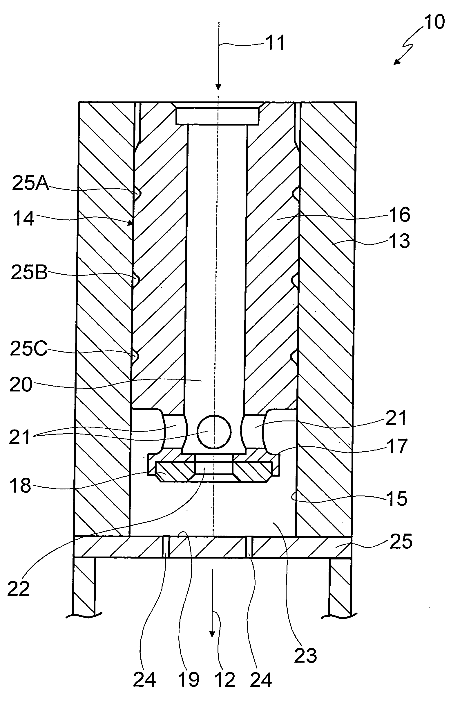
[0018] A gas valve 10 is shown in FIG. 1 which is designed for use in a fuel cell or a gas-powered engine of a motor vehicle and which is used for controlling a flow of hydrogen or NG (natural gas) from an inflow side 11 to an outflow side 12.

[0019] Gas valve 10 includes a valve housing 13 which has a multipart design and accommodates a solenoid coil (not shown) which is used for actuating a solenoid armature 14 which is guided in a longitudinally (axially) displaceable manner in a cylindrical recess 15 of valve housing 13.

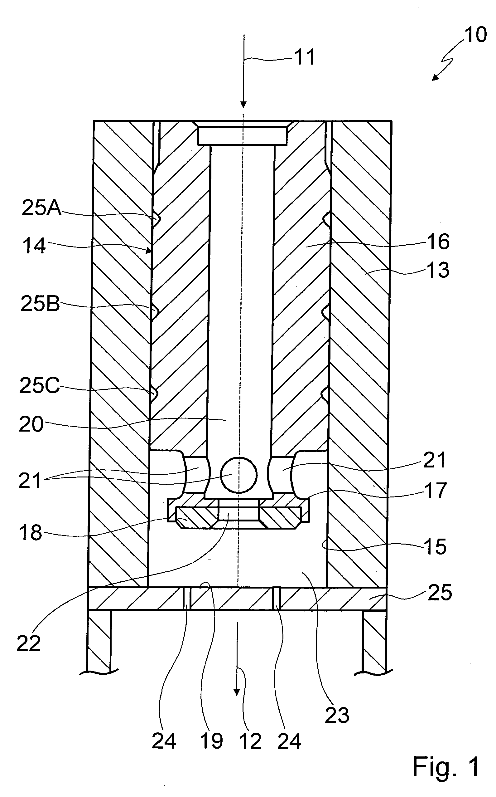
[0020] Solenoid armature 14 is designed essentially in the shape of a tube and has a cylindrical region 16 through which it is guided in receptacle 15 of valve housing 13 and which is adjacent to a region 17 designed as a valve-closing member having a smaller diameter which cooperates with a valve seat 19 via an elastomer seal 18 situated on the front face.

[0021] Solenoid armature 14 further includes an axially oriented internal space 20 which connects inflow s...


PUM


Abstract

A valve for controlling a fluid, in particular for controlling a gas. The valve includes a valve housing which accommodates an electromagnetic actuating unit for a solenoid armature which is guided axially displaceably in the valve housing and which cooperates with a valve seat via a valve-closing member, so that a fluid stream from an inflow side to an outflow side of the valve is controllable. At least one lubricant chamber adjacent to the guide gap between the valve housing and the solenoid armature is provided.

Description

FIELD OF THE INVENTION [0001] The present invention is directed to a valve for controlling a fluid, in particular for controlling a gas. BACKGROUND INFORMATION [0002] A valve of this type is known from practical experience and is usable as a gas control valve in a fuel cell and / or a gas-powered engine. [0003] A valve of this type includes a valve housing which may have a multipart design, and an electromagnetic actuating unit for a solenoid armature. The solenoid armature is guided axially displaceably in a receptacle of the valve housing having a matching design, and cooperates with a valve seat, so that a fluid stream from an inflow side to an outflow side of the valve is controllable. The solenoid armature is configured as valve-closing element on its end facing the valve seat. [0004] A known valve of this type has the disadvantage—in particular when used to control a dry gas—that material wear may occur in the guide region between the solenoid armature and the valve housing, whi...

Claims


Application Information

Patent Timeline
Patent Type & Authority Applications(United States)
IPC IPC(8): F16K31/06
CPCF16K31/0655F16K31/0651
Inventor DORNHOEFER, GERDBANTLEON, GUENTHERNGUYEN-SCHAEFER, THANH-HUNGMOELLER, MARTINHEBNER, THOMAS
Owner ROBERT BOSCH GMBH
Why Eureka
Try Eureka