DC-DC converter

Active Publication Date: 2005-04-28
TEXAS INSTR INC
View PDF3 Cites 32 Cited by
  • Summary
  • Abstract
  • Description
  • Claims
  • Application Information

AI Technical Summary

Benefits of technology

[0019] When the DC-DC converter of various aspects of the present invention is used, even if the input voltage varies quickly and abruptly within the scope of

Problems solved by technology

It is inappropriate to stop the operation of the entire control system for this instantaneous transition state, and the reliability will be compromised.
In other words, in the conventional DC-DC converter, a restoration process in which an external start command is applied after the output is shut down completely not only results in too much protec

Method used


Image

  • DC-DC converter
  • DC-DC converter
  • DC-DC converter

Examples


embodiment 1

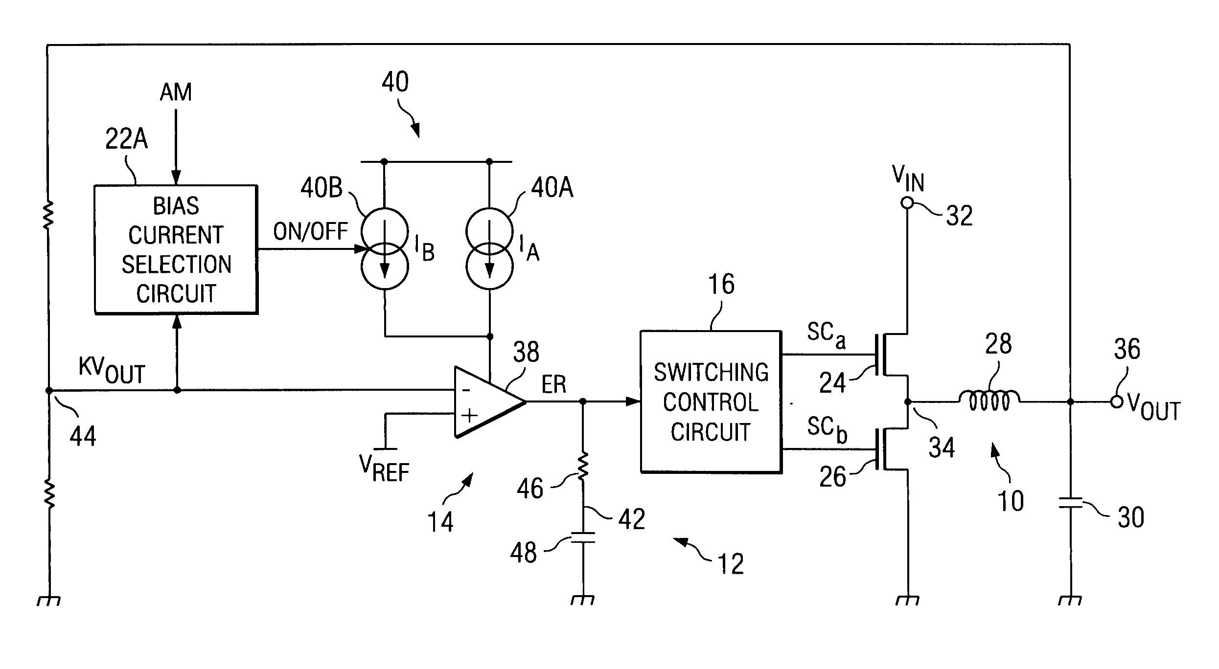
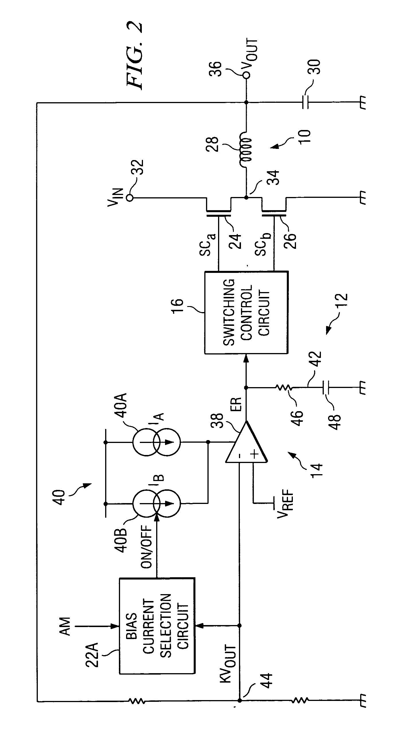
[0037]FIG. 2 shows the configuration of the DC-DC converter disclosed in the first embodiment of the present invention. In this DC-DC converter, switching power supply unit 10 is a step-down chopper. It has MOSFET 24 for main switching and MOSFET 26 for synchronous rectification as the switching elements. The rectifying and smoothing circuit is comprised of choke coil 28 and smoothing capacitor 30.

[0038] More specifically, one of the terminals of MOSFET 24 for main switching is connected to power supply input terminal 32, which inputs DC input voltage Vin. The other terminal is connected to switching output terminal (node) 34. One of the terminals of MOSFET 26 for synchronous rectification is connected to switching output terminal (node) 34, while the other terminal is connected to ground potential. One of the terminals of choke coil 28 is connected to switching output terminal (node) 34, while the other terminal is connected to power supply output terminal 36, which supplies the D...

embodiment 2

[0053]FIG. 5 shows the configuration of the DC-DC converter disclosed in the second embodiment. In this figure, the parts having the same configuration or same function as those described in the first embodiment (FIG. 2) are represented by the same symbols, respectively.

[0054] In the second embodiment, in error amplifier 14, a constant bias current I is supplied constantly from constant current source circuit 40 to differential amplifier 38. Under the control of output resistance selection circuit 22B that corresponds to response characteristic selection circuit 22 (FIG. 1), the resistance of output resistor 46 in output circuit 42 is switched between RA and (RA+RB) by a switch 50. The magnitudes and the ratio of RA and RB can be set as desired. For example, the ratio can be set to RA:RB=1:1.

[0055] In general, in a DC-DC converter, input voltage Vin might also drop significantly within the scope of the normal operating conditions. For example, when the plug (DC output terminal) of...


PUM


Abstract

A DC-DC converter, which can respond quickly and suitably to changes in input voltage within the scope of normal operating conditions to return to the normal operating state. The DC-DC converter is comprised of switching power supply unit 10, which can turn on/off switching elements that can be turned on/off at high frequency to convert a DC input voltage Vin into a DC output voltage Vout, and a control unit 12, which is used to control the on/off operation of the switching elements of said switching power supply unit 10. In control unit 12, when DC output voltage Vout is out of the range of monitoring value AM, the response characteristic of the feedback loop (especially the response characteristic of error amplifier 14) is switched to a greater responsivity to continue the switching control operation of the control system without stopping it.

Description

FIELD OF THE INVENTION [0001] The present invention pertains to a DC-DC converter that can convert from one input DC level (direct current) into another DC level (direct current). BACKGROUND OF THE INVENTION [0002] A DC-DC converter is a DC power supply that is small, lightweight, and highly efficient, and uses a semiconductor switching element. It is widely used in electronic devices, etc. In recent years, there has been a great demand for small, lightweight, and highly efficient power supplies. The basic principle of a DC-DC converter is that the switching element is turned on / off at high frequency, and the ratio of the on-time to off-time, that is, the duty ratio, is controlled in a variable manner to keep the DC output voltage at a certain level. Usually, the voltage is controlled to a constant level through negative feedback of the output voltage. More specifically, the output voltage is fed back and compared with a reference value by an error amplifier to find the error. A swi...

Claims


Application Information

Patent Timeline
IPC IPC(8): H02M3/155G05F1/40H02M3/156
CPCH02M1/32H02M3/156
Inventor ITOHARA, MITSURU
Owner TEXAS INSTR INC
Why Eureka
Try Eureka