
Temperature compensated power amplifier power control

a power amplifier and temperature compensation technology, applied in the direction of amplifiers, amplifiers with semiconductor devices only, amplifiers with semiconductor devices, etc., can solve the problems of affecting the performance of the polar modulation system, introducing errors into the output signal, and fluctuating output of the power amplifier, so as to achieve accurate and repeatable results, no fluctuations

Active Publication Date: 2005-04-28
QORVO US INC
View PDF46 Cites 68 Cited by
  • Summary
  • Abstract
  • Description
  • Claims
  • Application Information

AI Technical Summary

Benefits of technology

The present invention provides a system for compensating for temperature variations in a power amplifier by adjusting the supply voltage applied to the amplifier. This ensures that the amplifier provides an accurate and repeatable output signal with no fluctuations due to changes in temperature. The system uses a circuit that generates a reference voltage that varies with temperature, amplifies it, and regulates it to create the supply voltage. This ensures that the power amplifier operates optimally regardless of temperature variations. The system can be used in a polar modulation system or in a mobile communication device for power control. Overall, the invention improves the accuracy and reliability of power amplification in various applications.

Problems solved by technology

However, the output of the power amplifier fluctuates due to variations in the characteristics of the power amplifier caused by changes in temperature.
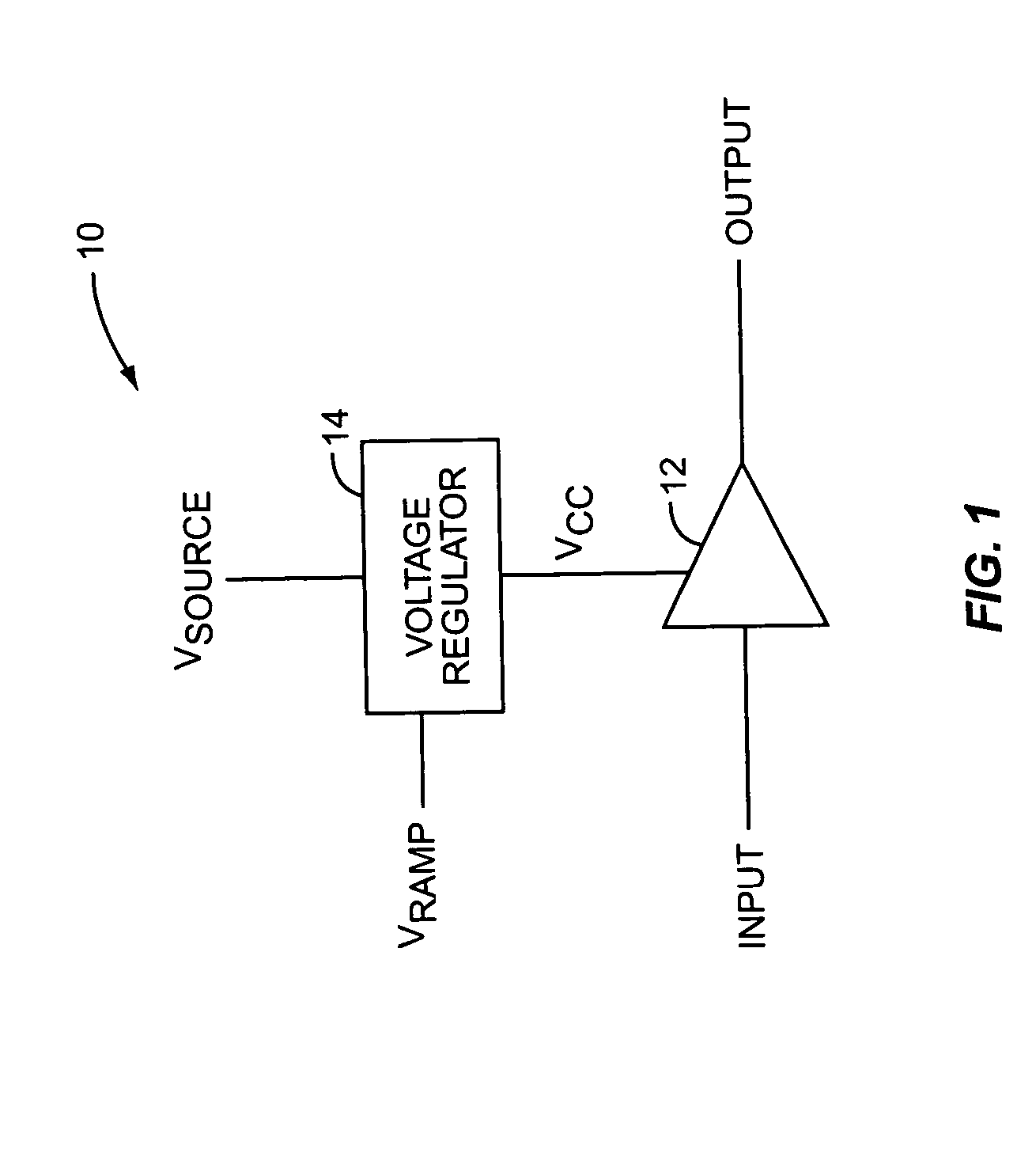
However, since the system 10 does not provide temperature compensation for the power amplifier 12, changes in temperature cause the output of the power amplifier 12 to fluctuate, thereby introducing error into the output signal (OUTPUT) and degrading the performance of the polar modulation system.
However, since the system 10 does not provide temperature compensation for the power amplifier 12, changes in temperature result in fluctuations in the output power of the power amplifier.

Method used


Image

  • Temperature compensated power amplifier power control
  • Temperature compensated power amplifier power control
  • Temperature compensated power amplifier power control

Examples


Embodiment Construction

[0020] The embodiments set forth below represent the necessary information to enable those skilled in the art to practice the invention and illustrate the best mode of practicing the invention. Upon reading the following description in light of the accompanying drawing figures, those skilled in the art will understand the concepts of the invention and will recognize applications of these concepts not particularly addressed herein. It should be understood that these concepts and applications fall within the scope of the disclosure and the accompanying claims.

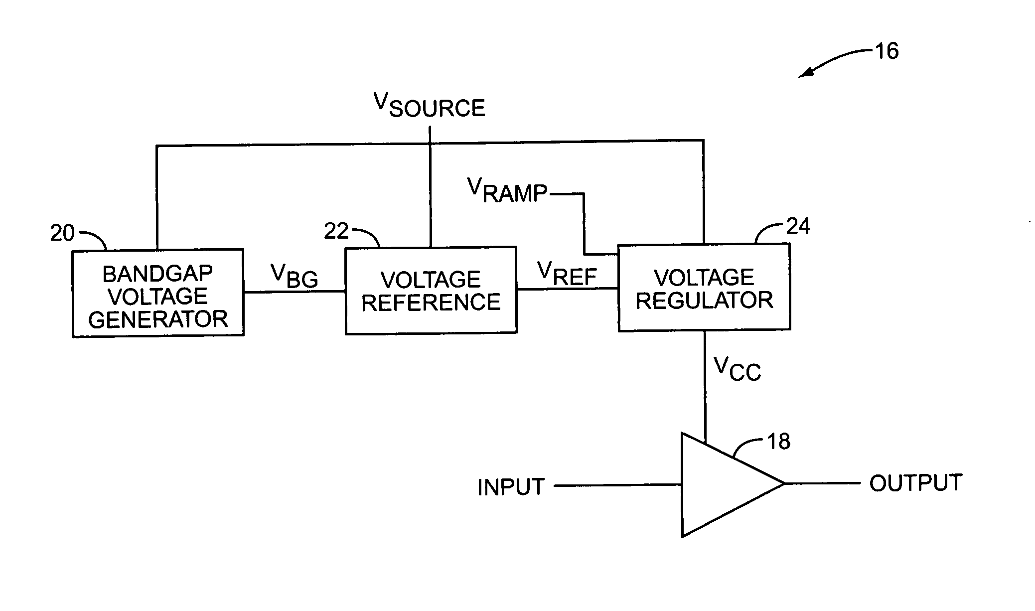
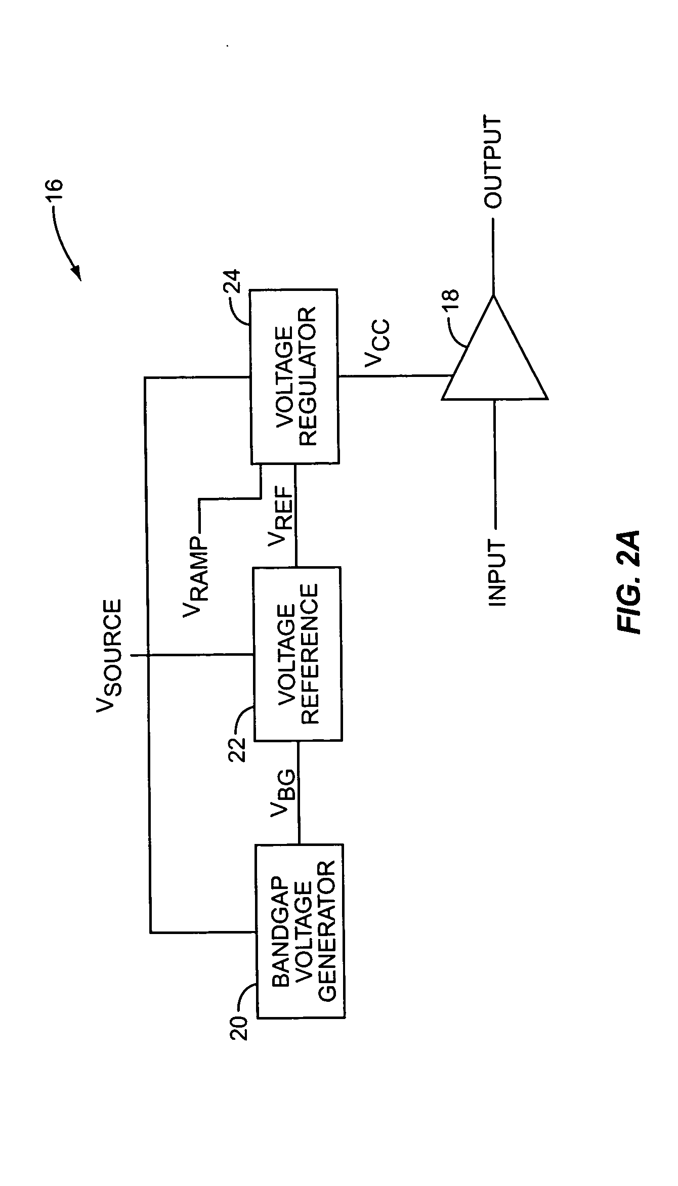
[0021]FIG. 2A illustrates a system 16 providing temperature compensation for a power amplifier 18 according to one embodiment of the present invention. The power amplifier 18 amplifies an input signal (INPUT) and provides an accurate and repeatable output signal (OUTPUT) having essentially no fluctuations due to temperature variations. In general, the system 16 includes the power amplifier 18, a bandgap voltage generator 20, a v...


PUM


Abstract

The present invention provides temperature compensation for a power amplifier by varying a supply voltage applied to the power amplifier. The supply voltage is varied based on operating temperature in light of the temperature characteristics of the power amplifier. Thus, the variation in the supply voltage offsets variations in the characteristics of the power amplifier due to changes in temperature. Whether the power amplifier is used to control the output power of a transmitter or as part of a polar modulation system, temperature compensation of the power amplifier allows the power amplifier to provide an accurate and repeatable output signal having essentially no fluctuations due to changes in temperature.

Description

FIELD OF THE INVENTION [0001] The present invention relates to power amplifiers, and more specifically to compensating for variations in the characteristics of the power amplifier due to variations in temperature. BACKGROUND OF THE INVENTION [0002] There are several standards for mobile telephone communications. Each of these standards requires precise output power control over a large dynamic range. In order to provide output power control, mobile telephone architectures typically employ one or more power amplifiers that amplify a signal prior to transmission. However, the output of the power amplifier fluctuates due to variations in the characteristics of the power amplifier caused by changes in temperature. Thus, in order to provide precise output power control over a large dynamic range, some form of temperature compensation is desirable to compensate for variations in the output of the power amplifier due to variations in the characteristics of the power amplifier caused by cha...

Claims


Application Information

Patent Timeline
Patent Type & Authority Applications(United States)
IPC IPC(8): H03F1/02H03F1/30
CPCH03F1/0222H03F2200/504H03F2200/447H03F1/30
Inventor GAMERO, CARLOSBOSLEY, RYAN
Owner QORVO US INC
Learn More