Dynamic window anatomy

a dynamic window and anatomy technology, applied in the direction of user interface execution, static indicating devices, instruments, etc., can solve the problems of limited capacity to present visually rich content or exploit enhancements in graphical rendering technology, limiting the potential for graphics hardware-based acceleration, and other features such as transparency, shadows, advanced lighting effects, etc., to achieve the effect of reducing the difficulty of rendering and rendering, and reducing the cost of rendering

Active Publication Date: 2005-04-28
MICROSOFT TECH LICENSING LLC
View PDF20 Cites 157 Cited by
  • Summary
  • Abstract
  • Description
  • Claims
  • Application Information

AI Technical Summary

Problems solved by technology

A drawback to many prior graphical user interface desktop implementations is their limited capacity to present visually rich content or exploit enhancements in graphical rendering technology.
However, because windows on the desktop are rendered in a top-down order, features such as non-rectangular windows and rich 2D animations via GDI require CPU intensive calculations involving complex regions and / or extensive sampling of the display surface (thereby limiting the potential for graphics hardware-based acceleration), whereas other features such as transparency, shadows, 3D graphics and advanced lighting effects are extremely difficult and very resource intensive.
However, desktop compositing is a memory intensive process because the CDWM maintains in memory a copy of each item drawn to the desktop.
Prior to recent market changes and manufacturing techniques that have made advanced video hardware and computer memory far more affordable, only commercial, expensive, high-end computing systems have been able to implement compositing engines, such as for preparing special effects for movies.
However, the graphical services available in popular operating systems have not significantly advanced for a variety of reasons, including the need to maintain compatibility with older application software and the limited capabilities of the affordable range of video hardware.
Another obstacle in implementing a compositing desktop model is that legacy applications written for use with an invalidation model DWM will not function property in a compositing environment.
The most difficult remedy consists of devising a means by with the compositing DWM surrogates the legacy GUI platform on behalf of the application.
Presently, UI elements residing in the non-client area cannot be modified by the application.
In addition, there is no straightforward and robust means to query, modify, or selectively override the standard frame layout, or render non-client elements individually.
For example, there is no practical way for an application to relocate the system icon or non-client buttons (e.g., restore, maximize, minimize, close) and add or track custom non-client buttons.
In addition, applications are limited to placing application content in a single rectangular region (the client area) unless the application wants to assume rendering and hit-testing responsibility for the entire non-client area (as well as the client area) of the window.
Loosening any of these restrictions within the existing USER framework would render unusable many popular legacy applications that anticipate and depend on them.

Method used


Image

  • Dynamic window anatomy
  • Dynamic window anatomy
  • Dynamic window anatomy

Examples


Embodiment Construction

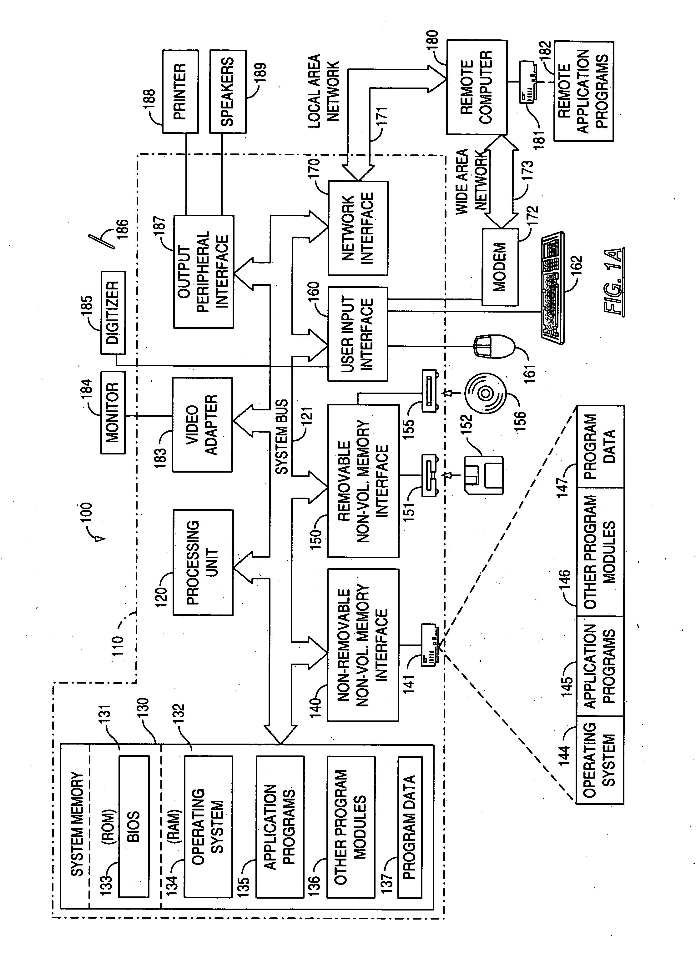
[0027] In the following description of the various embodiments, reference is made to the accompanying drawings, which form a part hereof, and in which is shown by way of illustration various embodiments in which the invention may be practiced. It is to be understood that other embodiments may be utilized and structural and functional modifications may be made without departing from the scope and spirit of the present invention.

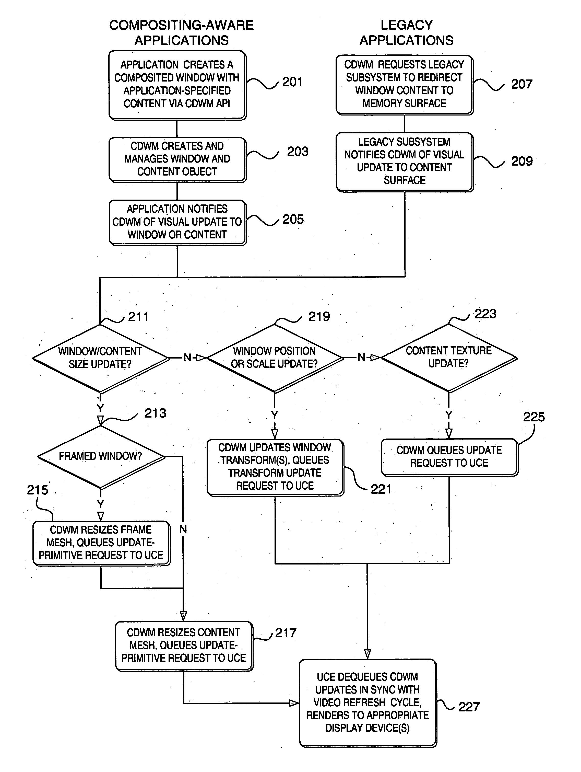
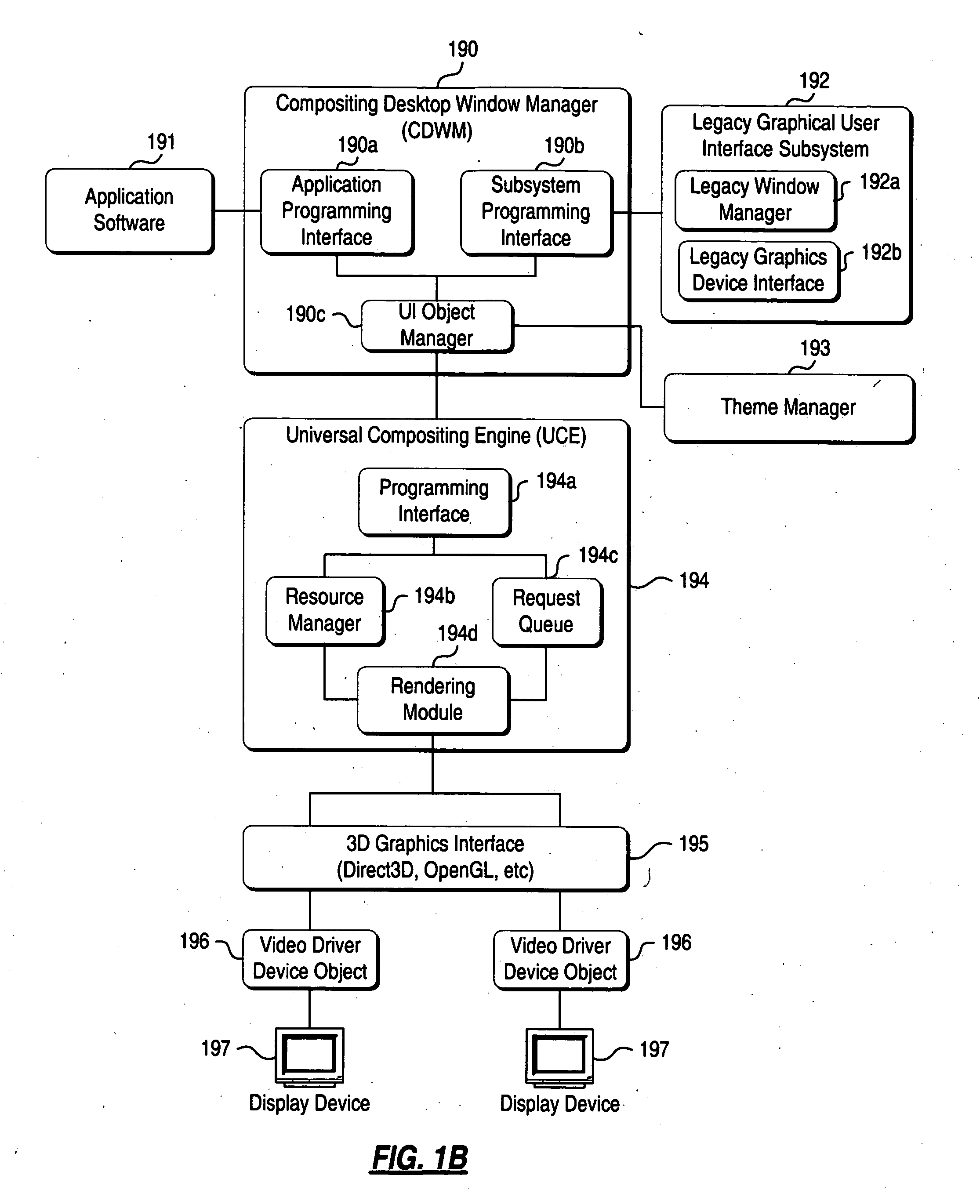
[0028] The present invention provides a desktop window manager (DWM) that uses desktop compositing as its preferred rendering model. The inventive desktop window manager is referred to herein as a Compositing Desktop Window Manager (CDWM). The CDWM, together with the composition subsystem, referred to as the Unified Compositing Engine (UCE), provides 3D graphics and animation, shadows, transparency, advanced lighting techniques and other rich visual features on the desktop. The compositing rendering model used herein intrinsically eliminates the invalidation ...


PUM


Abstract

A method and system for rendering a desktop on a computer using a composited desktop model operating system are disclosed. A composited desktop window manager, upon receiving base object and content object information for one or more content objects from an application program, draws the window to a buffer memory, and takes advantage of advanced graphics hardware and visual effects to render windows based on content on which they are drawn. The frame portion of each window may be generated by pixel shading a bitmap having the appearance of frosted glass based on the content of the desktop on top of which the frame is displayed. Legacy support is provided so that the operating system can draw and render windows generated by legacy applications to look consistent with non-legacy application windows.

Description

FIELD OF THE INVENTION [0001] The invention relates generally to a graphical user interface of a computer operating system. More specifically, the invention provides a mechanism that allows for the possibility of having, on a window-by-window basis, multiple and / or irregularly-shaped client and non-client content areas in each window. BACKGROUND OF THE INVENTION [0002] Computer operating systems typically have a shell that provides a graphical user interface (GUI) to an end-user. The shell consists of one or a combination of software components that provide direct communication between the user and the operating system. The graphical user interface typically provides a graphical icon-oriented and / or menu driven environment for the user to interact with the operating system, and is often based on a desktop metaphor. More specifically, the graphical user interface is designed to model the real world activity of working at a desk. The desktop environment typically occupies the entire s...

Claims


Application Information

Patent Timeline
Patent Type & Authority Applications(United States)
IPC IPC(8): G06F3/048G09G5/14
CPCG06F3/0481G09G5/14G06F9/4443G06F9/451G06F3/14
Inventor HANGGIE, SCOTTTAN, VICTORBERMUDEZ, GERARDOSWEDBERG, GREGORY D.
Owner MICROSOFT TECH LICENSING LLC
Why Eureka
Try Eureka