Electro-optic modulator on rib waveguide

a technology of optical modulator and rib waveguide, which is applied in the direction of optical waveguide light guide, instruments, optics, etc., can solve the problems of reducing the effectiveness of the thermo-optic effect, unable to use up to 1 mhz modulation frequency, and undesirable long interaction lengths

Inactive Publication Date: 2005-04-28
CORNELL RES FOUNDATION INC
View PDF7 Cites 70 Cited by
  • Summary
  • Abstract
  • Description
  • Claims
  • Application Information

AI Technical Summary

Benefits of technology

[0008] An electro-optic modulator is formed on a silicon-on-insulator (SOI) rib waveguide. An optical field in the modulator is confined by using an electrically modulated microcavity. The microcavity has reflectors on each side. In one embodiment, a planar Fabry-Perot microcavity is used with deep Si/SiO2 Bragg reflectors. Carriers may be

Problems solved by technology

Nevertheless, the thermo-optic effect is rather slow and can only be used up to 1 MHz modulation frequencies.
Long interaction lengths are undesirable in order to achieve high levels of integration and miniaturization for fabricating low-

Method used


Image

  • Electro-optic modulator on rib waveguide
  • Electro-optic modulator on rib waveguide
  • Electro-optic modulator on rib waveguide

Examples


Embodiment Construction

[0014] In the following description, reference is made to the accompanying drawings that form a part hereof, and in which is shown by way of illustration specific embodiments in which the invention may be practiced. These embodiments are described in sufficient detail to enable those skilled in the art to practice the invention, and it is to be understood that other embodiments may be utilized and that structural, logical and electrical changes may be made without departing from the scope of the present invention. The following description is, therefore, not to be taken in a limited sense, and the scope of the present invention is defined by the appended claims.

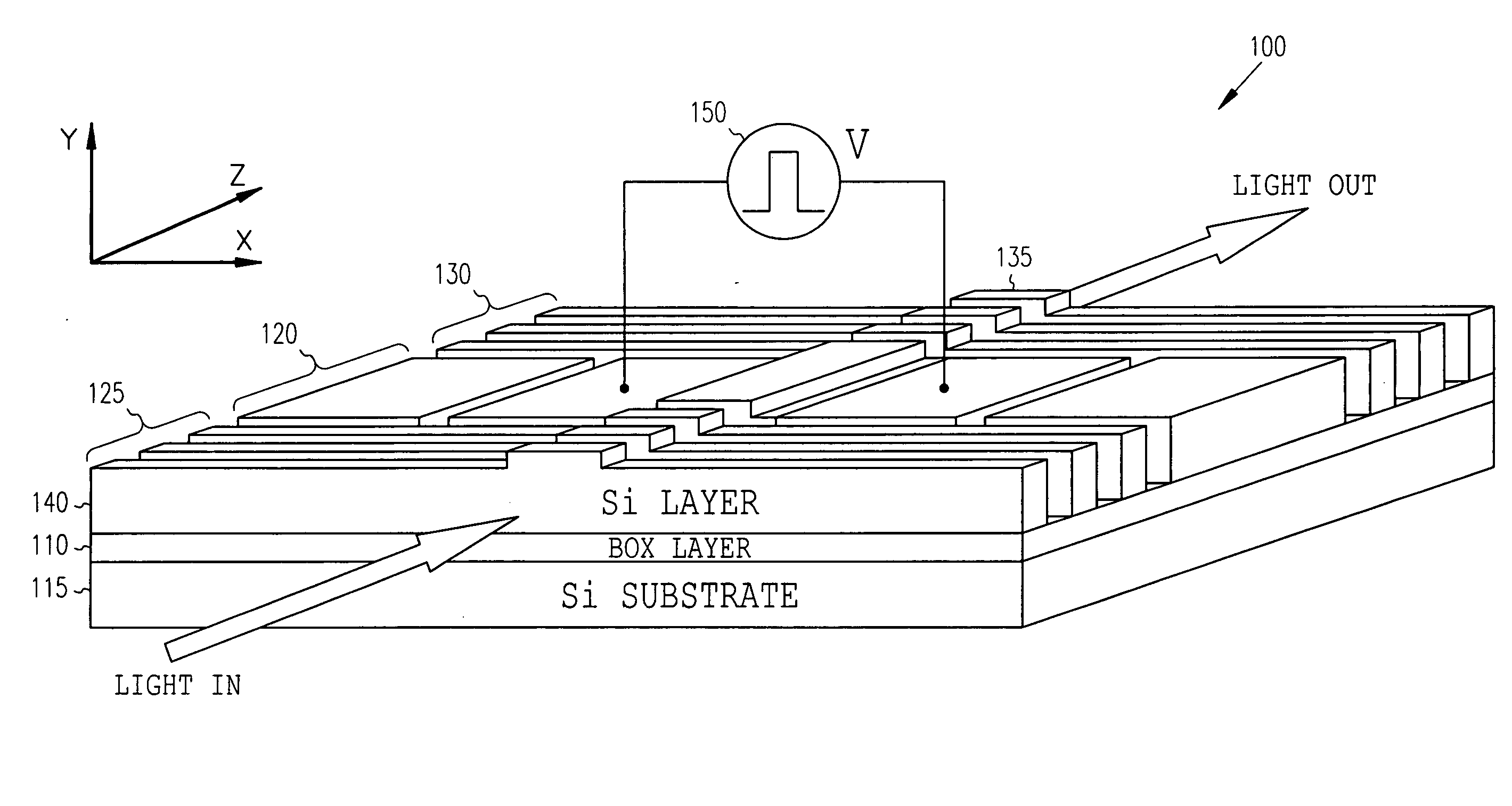
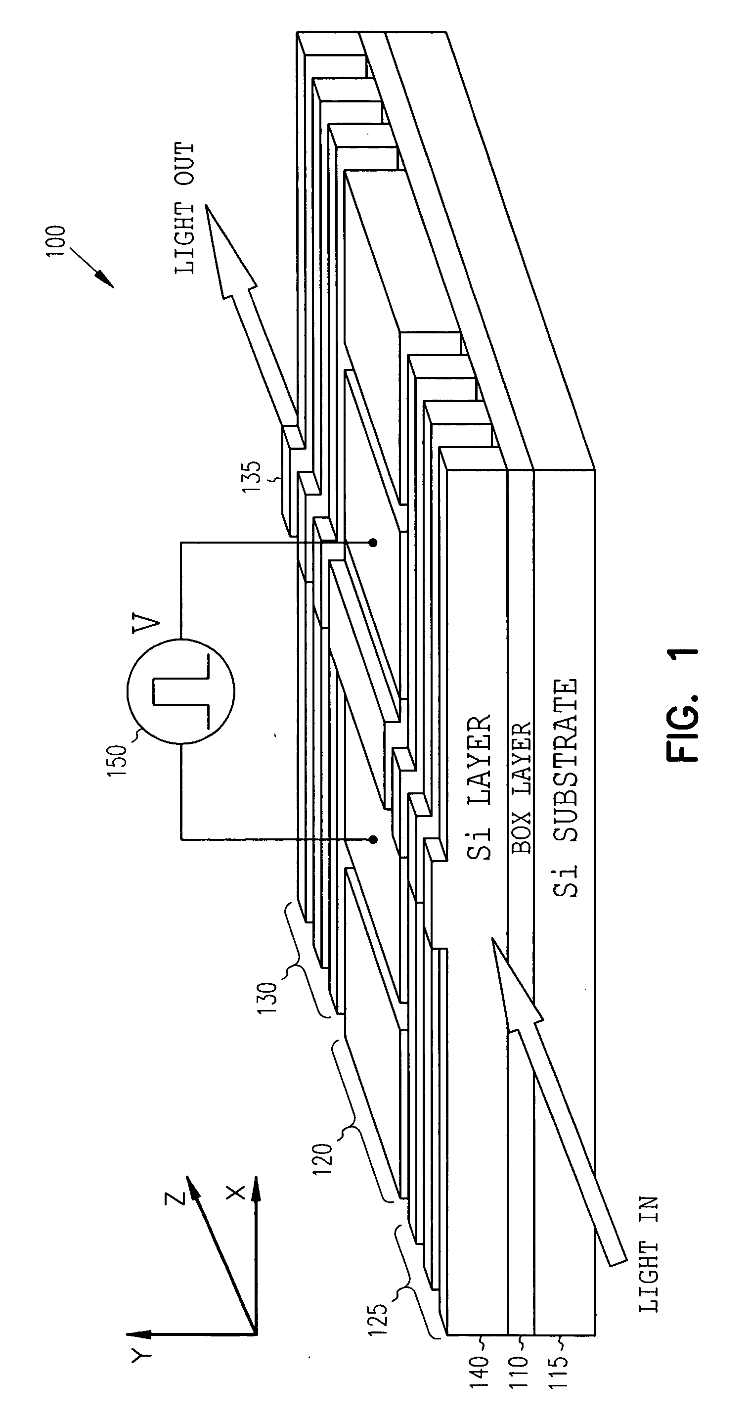
[0015]FIG. 1 shows a perspective block schematic view of a partially finished electro-optic modulator 100. The structure will be described first, followed by a fabrication description and a description of potential operating principles and characteristics of various embodiments. For ease of illustration, an SiO2 layer coveri...


PUM


Abstract

An electro-optic modulator is formed on a silicon-on-insulator (SOI) rib waveguide. An optical field in the modulator is confined by using an electrically modulated microcavity. The microcavity has reflectors on each side. In one embodiment, a planar Fabry-Perot microcavity is used with deep Si/SiO2 Bragg reflectors. Carriers may be laterally confined in the microcavity region by employing deep etched lateral trenches. The refractive index of the microcavity is varied by using the free-carrier dispersion effect produced by a p-i-n diode formed about the microcavity. In one embodiment, the modulator confines both optical field and charge carriers in a micron-size region.

Description

RELATED APPLICATION [0001] This application claims priority to U.S. Provisional Application Ser. No. 60 / 461,705 (entitled Low-Power-Consumption Short-Length and High-Modulation-Depth Silicon Electro-Optic Modulator, filed Apr. 9, 2003) which is incorporated herein by reference.GOVERNMENT FUNDING [0002] The invention described herein was made with U.S. Government support under Contract Number F49620-02-1-0396 awarded by Defense Advanced Research Project Agency. The United States Government has certain rights in the invention.FIELD OF THE INVENTION [0003] The present invention relates to an electro-optic modulator, and in particular to an electro-optic modulator formed on a rib waveguide. BACKGROUND OF THE INVENTION [0004] Silicon-based photonic components working at 1.3 and 1.55-μm fiber-optic communications-wavelengths for fiber-to-home interconnects and local area networks (LAN) are a subject of intensive research because of the possibility of integrating optical elements and advan...

Claims


Application Information

Patent Timeline
IPC IPC(8): G02F1/015G02F1/025
CPCG02F2201/307G02F1/025
Inventor BARRIOS, CARLOS ANGULOLIPSON, MICHALALMEIDA, VILSON ROSA DE
Owner CORNELL RES FOUNDATION INC
Why Eureka
Try Eureka