
Drainage pump and underwater bearing unit

a technology of underwater bearings and pumps, which is applied in the direction of sliding contact bearings, machines/engines, liquid fuel engines, etc., can solve the problems of increasing the cost of bearing units, affecting the service life of bearing units, so as to improve the wear resistance of thermoplastic resin materials, reduce the need for checking the deterioration of oil conditions, and improve the service life.

Inactive Publication Date: 2005-04-28
HITACHI PLANT TECH LTD
View PDF5 Cites 4 Cited by
  • Summary
  • Abstract
  • Description
  • Claims
  • Application Information

AI Technical Summary

Benefits of technology

[0023] According to the invention, pumped water mixed with hard particles is used as a lubricant and a portion of a rotary shaft journaled by the sliding bearing is formed of a cemented carbide alloy material and a shaft journaling surface of the sliding bearing is formed of a thermoplastic resin material to be embedded with the hard particles. Hence, it is possible to provide a drainage pump and an underwater bearing unit employing a sliding bearing that can provide maintenance-free performance and enhance wear resistance to hard particles mixed in the pumped water and prevent abrasive wear and avoid the occurrence of cracks and damages caused by heat shock.
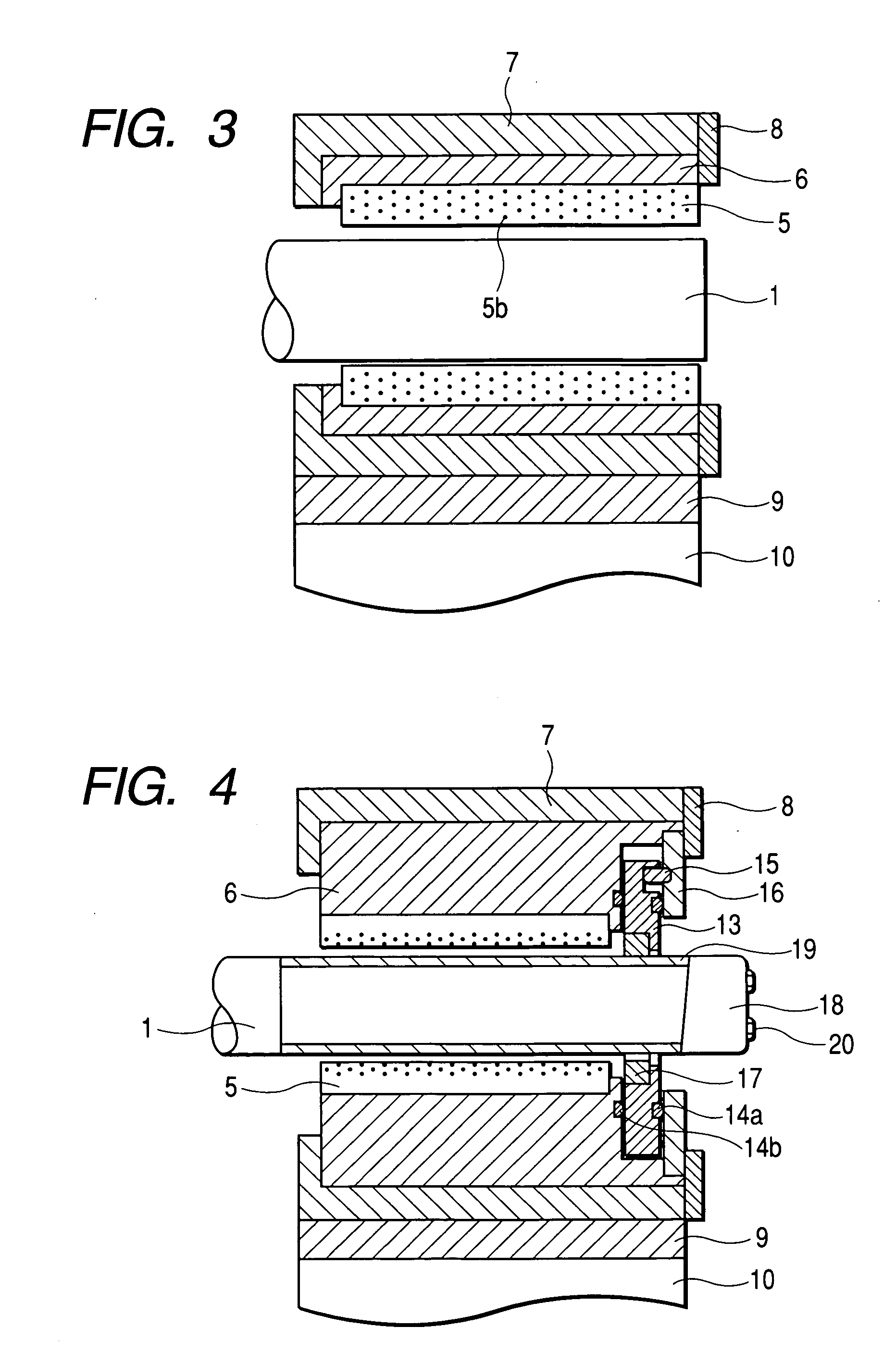
[0032] According to above-described preferable construction of the invention, a sleeve made of a cemented carbide alloy material is put onto the rotary shaft from one side end of the rotary shaft and a positioning member for holding the sleeve made of the cemented carbide alloy material is removably mounted on the one side end of the rotary shaft. Hence, in case of the sleeve made of the cemented carbide alloy material being damaged, the positioning member is removed and the sleeve made of the cemented carbide alloy material can be replaced. Therefore, reliability can be improved.

Problems solved by technology

However, the patent documents 1, 2 disclose that the local contact of the ceramic bearing is prevented but do not disclose that the bearing is damaged by hard particles mixed in pumped water used as a lubricant.
In the bearings disclosed in the patent documents 1, 2, in a case where hard particles are mixed in the pumped water used as a lubricant, there is a possibility that the bearing part might be damaged by the hard particles.
This type of bearing has a problem that, in order to surely prevent oil from flowing outside the bearing, a seal structure of high reliability is indispensably required to increase the cost of a bearing unit.
Hence, it cannot be said that this type of bearing gives sufficient consideration to maintenance-free performance.

Method used


Image

  • Drainage pump and underwater bearing unit
  • Drainage pump and underwater bearing unit
  • Drainage pump and underwater bearing unit

Examples


Embodiment Construction

[0037] Hereafter, a plurality of embodiments of the present invention will be described by use of drawings. In the second embodiment and the following embodiments, a duplicate description of construction common to the first embodiment will be omitted. In this regard, like reference symbols in the drawings of the respective embodiments designate like or corresponding parts. While a case where a PTFE base thermoplastic resin is used as a resin material of a bearing part will be described here, there is no limit to the kind of a material if the material is a thermoplastic resin material.

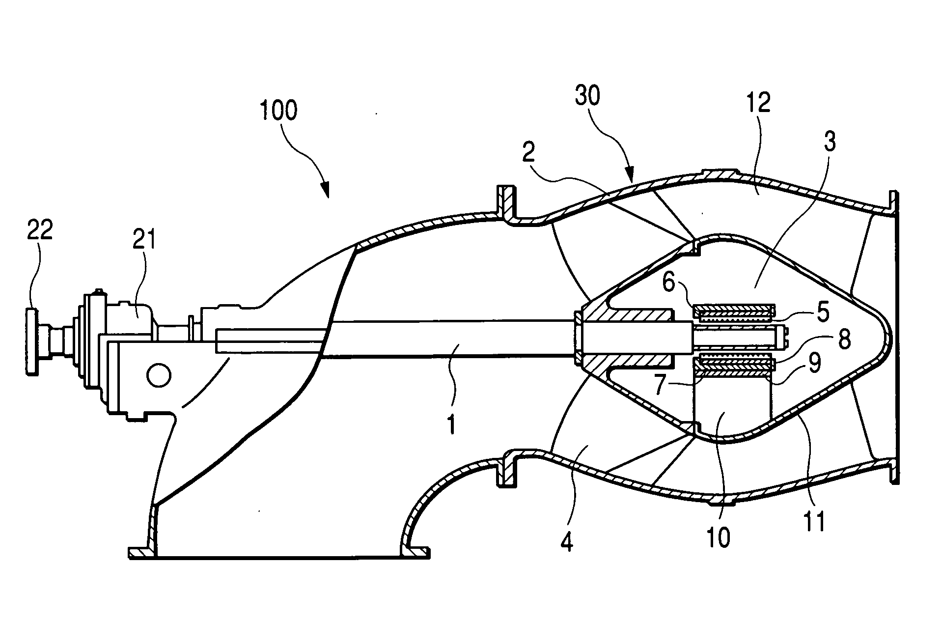
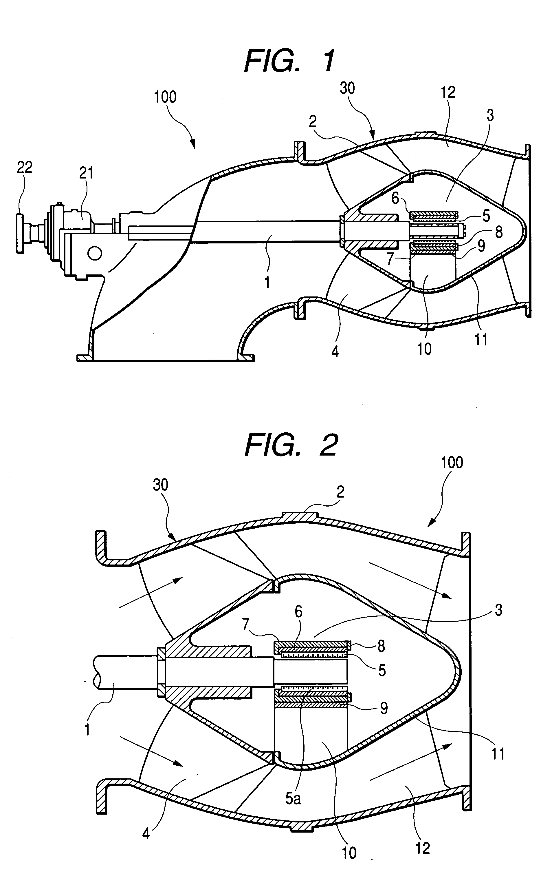
[0038] First, the first embodiment of the present invention will be described by use of FIG. 1 to FIG. 3. FIG. 1 is a longitudinal cross-sectional view of a horizontal drainage pump in accordance with the first embodiment of the invention and FIG. 2 is an enlarged view of a main portion in FIG. 1.

[0039] A horizontal drainage pump 100, as shown in FIG. 1, is constructed of a pump part 30, an underwater...


PUM


Abstract

A drainage pump has a pump part in which blades mounted on a rotary shaft are arranged in a pump casing and an underwater bearing unit which uses pumped water mixed with hard particles as a lubricant and has a sliding bearing for journaling the rotary shaft. A portion of the rotary shaft journaled by the sliding bearing is formed of a cemented carbide material and a shaft journaling surface of the sliding bearing is formed of a thermoplastic resin material to be embedded with hard particles.

Description

CLAIM OF PRIORITY [0001] The present application claims priority from Japanese application serial no. 2003-364053, filed on Oct. 24, 2003, the content of which is hereby incorporated by reference into this application. FIELD OF THE INVENTION [0002] The present invention relates to a drainage pump and an underwater bearing unit and, in particular, is suitable for a drainage pump and an underwater bearing unit in which pumped water mixed with hard particles is used as a lubricant. BACKGROUND OF THE INVENTION [0003] A combination of a rolling bearing provided outside a pump casing and a sliding bearing that is provided in a pumped water path (in a pump casing) and uses pumped water mixed with hard particles as a lubricant has been widely used as a bearing for journaling the main shaft of a horizontal drainage pump. [0004] One of sliding bearings is a ceramic bearing having excellent wear resistance as disclosed in Japanese Unexamined Utility Model Publication No. S62(1987)-194919 (Pate...

Claims


Application Information

Patent Timeline
Patent Type & Authority Applications(United States)
IPC IPC(8): F04D3/00F04D29/02F04D29/046F04D29/04F04D29/047F16C17/14F16C33/12F16C33/20
CPCF04D29/047F04D3/00
Inventor AIZAWA, KOUJIKISHIMOTO, SHIGERUTAKAGI, KANAMEIWASAKI, MINORUTAGAWA, TOMOHIKO
Owner HITACHI PLANT TECH LTD
Learn More