Refrigeration purifiers

a technology of refrigerating purifier and purifier body, which is applied in the direction of cleaning hollow articles, specific water treatment objectives, heating types, etc., can solve the problems of wasting produce in refrigerated spaces, water wastage, and pollutant accumulation in liquid or frozen water

a technology of refrigerating purifier and purifier body, which is applied in the direction of cleaning hollow articles, specific water treatment objectives, heating types, etc., can solve the problems of wasting produce in refrigerated spaces, water wastage, and pollutant accumulation in liquid or frozen water

US20050089458A1Inactive Publication Date: 2005-04-28OZONE MFG

Image

  • Refrigeration purifiers
  • Refrigeration purifiers
  • Refrigeration purifiers

Examples


Embodiment Construction

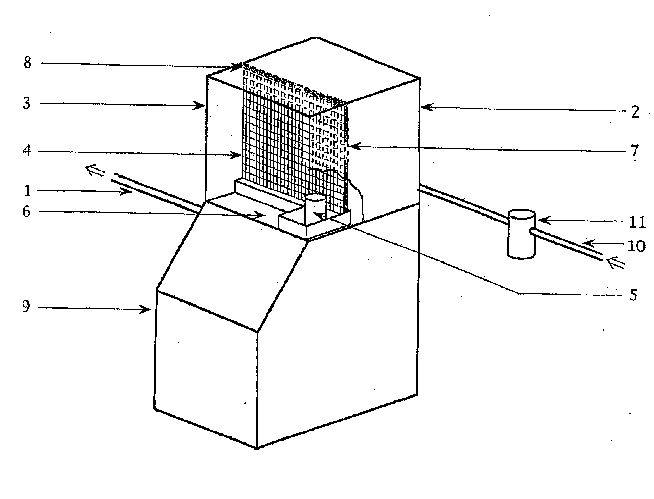
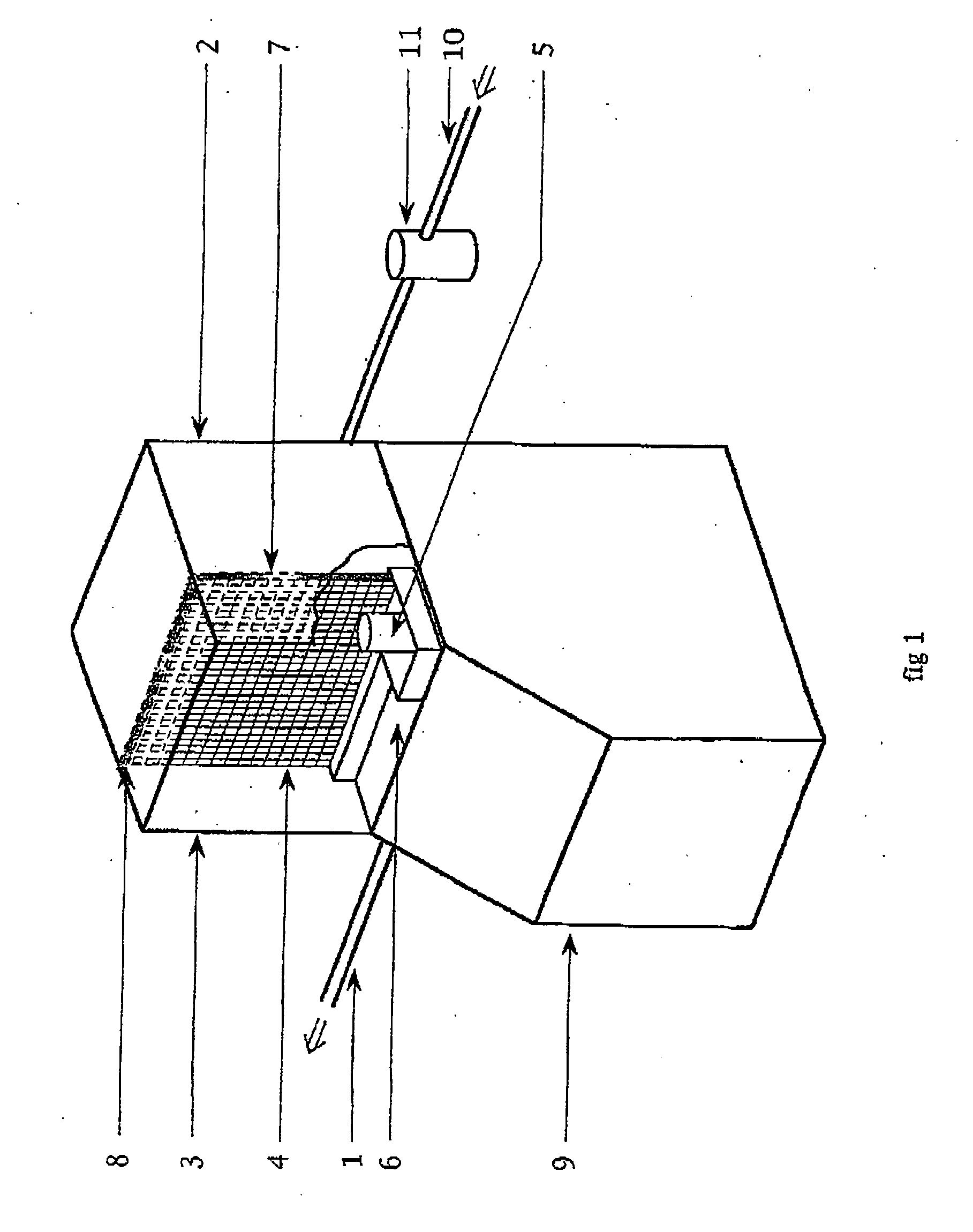
[0043]FIG. 3 shows an example of how the Purifier 12 can be located in a refrigeration machine, such as an ice machine. The Purifier can be fastened or hung in any position. It can be located on the outside of the chamber in position 12, to allow easy installation or it can be located inside the refrigeration chamber in position 13 or inside the ice rack chamber in position 14.

[0044] The Purifier has an inlet hole 15, which delivers air to it, preferably from a location where the air is relatively dry such as the outside of the product. A small tube and air filter may be attached to this inlet hole. The Purifier also has an outlet tube 16 to deliver the oxidants to the water, preferably in the reservoir 6, where it is dissolved in the water preferably by using a porous diffuser 17. Alternatively the diffuser can be a long device and located at position 18 in the reservoir under the ice tray. The Purifier is connected to an electrical supply, such as the terminals of the ice machine...


PUM

PropertyMeasurementUnit
Flow rateaaaaaaaaaa
Concentrationaaaaaaaaaa
Electrical conductoraaaaaaaaaa

Abstract

A method and apparatus for the continuous or periodic cleaning and purification of water or air or surfaces in refrigeration systems, such as ice machines and refrigerated containers. Oxidants and oxidant radicals are produced electrically in a stream of air and the resultant gas is injected into a stream of water or air which flows through the refrigeration system and where further oxidants may be generated in this downstream flow of water or air.

Description

[0001] Refrigeration Purifiers are products, which control the quality of air, water and surfaces in refrigeration systems. These systems comprise a refrigeration unit or plant, which is used to cool air or water or produce. The refrigeration unit may be an integral part of a refrigeration machine (such as an Ice Machine) or may be used to create a refrigerated space (such as a Cool Room),. BACKGROUND OF THE INVENTION [0002] Refrigerated machines include Ice Machines, Drinking Water Coolers and Water Fountains. Such machines contain water and various electrical and mechanical components. The water may be recirculated and / or may interface with air. Therefore pollutants may build up in the liquid or frozen water, on component surfaces and in air spaces either within the machine or at exit points from the machine. Pollutants can include microorganisms, organic load, scale, off-odours, off-tastes and off-colours. Some refrigerated machines purge water to control pollutants and therefore...

Claims


Application Information

Patent Timeline
28 Apr 2005
Publication
US20050089458A1
IPC
A61L2/18; A61L2/20; F25D23/00; A61L9/015; A61L9/22; B01J19/08; B08B9/02; C01B13/10; C02F1/50; C02F1/72; C02F1/78; F25C1/12; F25D17/04
CPC
A61L2/202; F25D2400/22; B08B9/0327; B08B2203/005; B08B2230/01; C02F1/72; C02F1/78; C02F2103/023
Inventors
OKE, SIMON FORBES