Hydrophobic vent incorporated into cerebral spinal fluid drainage chamber

a technology of cerebral spinal fluid and drainage chamber, which is applied in the direction of wound drains, intravenous devices, etc., can solve the problems of patient's brains with potentially serious adverse effects and compromised venting ability, and achieve the effect of preventing the ingress

Inactive Publication Date: 2005-04-28
MEDTRONIC INC
View PDF21 Cites 12 Cited by
  • Summary
  • Abstract
  • Description
  • Claims
  • Application Information

AI Technical Summary

Benefits of technology

[0031] It is a further primary objective of the invention to produce a vent that per

Problems solved by technology

This configuration produces a vent that withstands CSF exposure without forming an “airlock” and the corresponding compromised venting capability.
If microbes get into the dr

Method used


Image

  • Hydrophobic vent incorporated into cerebral spinal fluid drainage chamber
  • Hydrophobic vent incorporated into cerebral spinal fluid drainage chamber
  • Hydrophobic vent incorporated into cerebral spinal fluid drainage chamber

Examples


Embodiment Construction

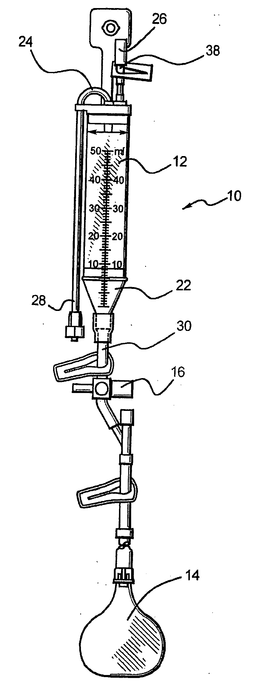
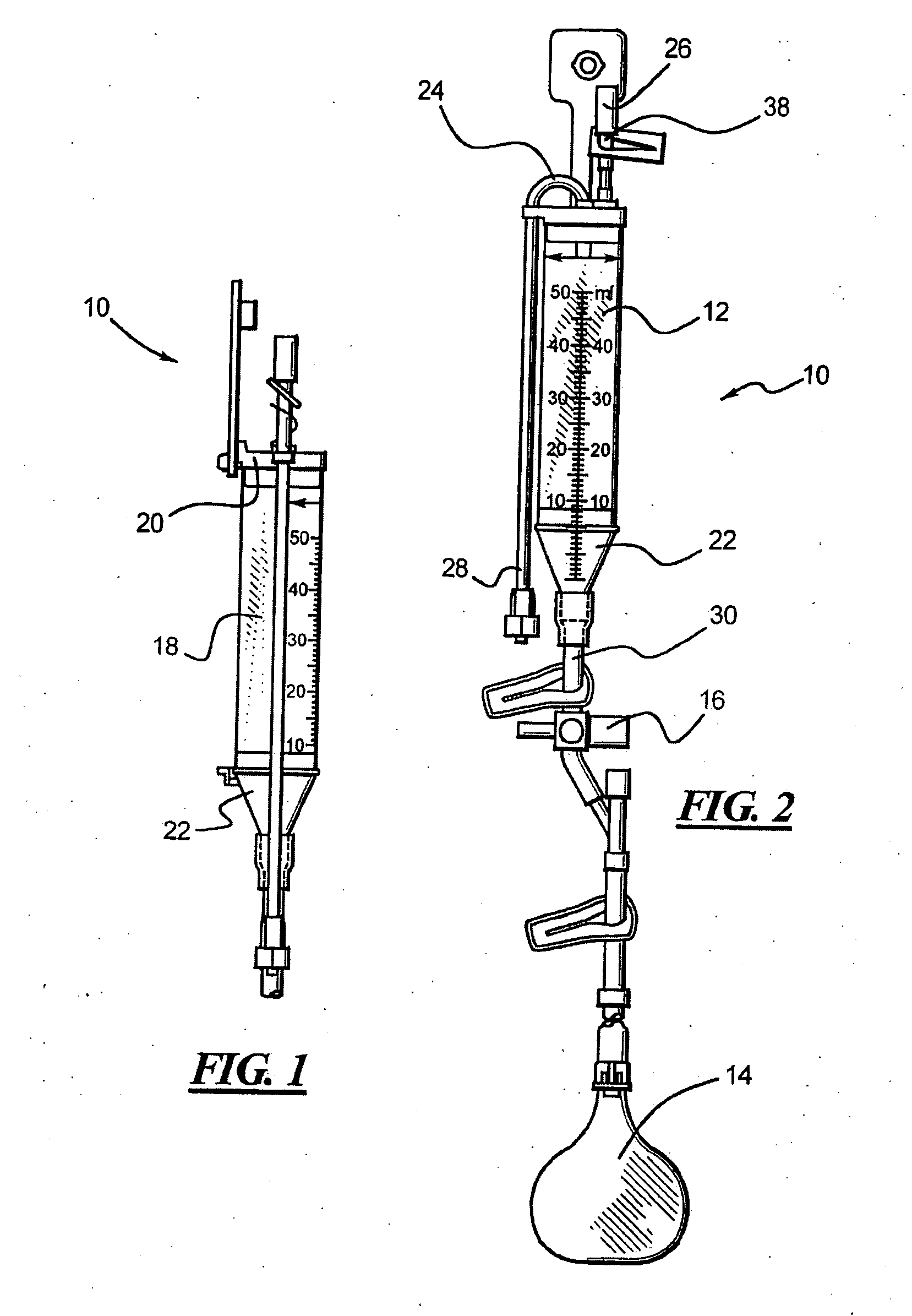
[0041] A CSF drainage system incorporating the present invention is shown in FIG. 4 generally labeled 40. The system includes a rigid drip chamber 12 and a drainage bag 14. A stopcock 16 connects drip chamber 12 to drainage bag 14.

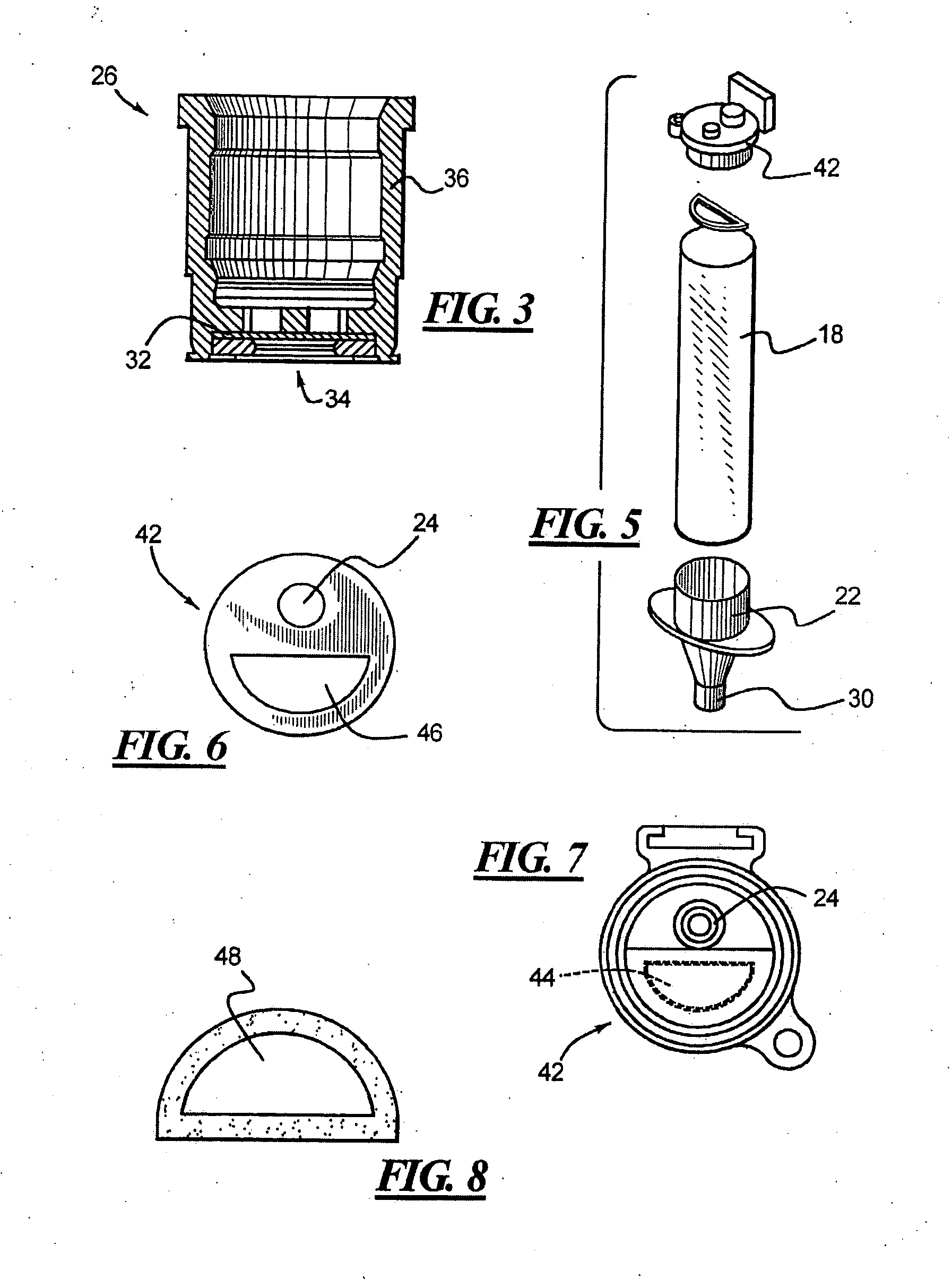
[0042] As mentioned, drip chamber 12 is made of a generally cylindrical, rigid tube 18 and includes an outlet manifold 22. Drip chamber 12 also has an inlet manifold 42 that is slightly different from inlet manifold 20. Inlet manifold 42 also has an inlet 24 but has a vent 44 that is different than vent 26 as will be described hereafter. Inlet 24 is connected through tubing 28 to a shunt (not shown) placed in a patient's head that drains CSF from the patient's ventricle. Outlet manifold 22 has an outlet 30 that is connected to stopcock 16.

[0043] Vent 44 is formed by covering a hole 46 in inlet manifold 42 with a porous, hydrophobic material 48. Material 48 is adhered to the inside surface of the inlet manifold 42. In the preferred embodiment, material 48...


PUM


Abstract

The invention comprises several aspects which are each independently useful or which may be combined in a variety of combinations. One aspect of the invention is placing an atmospheric reference vent at or near the top of a rigid drip chamber for draining CSF from a patient. In the preferred embodiment, the vent is placed on the inside of the drip assembly, immediately next to the CSF. The vent, in another aspect of the invention, is made of a hydrophobic material. In the preferred embodiment, the hydrophilic material is expanded polytetraflouroethylene (e-PTFE). In yet another aspect of the invention, the vent is made of a porous material having a pore size that allows air to readily pass through while preventing CSF from passing through. A preferred embodiment of this aspect includes making the vent of expanded polytetraflouroethylene (e-PTFE) with a pore size ranging from about 0.22 μm to about 5.0 μm and more preferable a pore size of about 3 μm. With this pore size, the vent also preferably has a surface area ranging from about 0.5 cm2 to about 5.0 cm2.

Description

BACKGROUND OF THE INVENTION [0001] 1. Field of the Invention [0002] This invention relates to a device for draining excess cerebral spinal fluid from a patient's brain and more particularly relates to a device for venting a rigid drip chamber used to drain excessive cerebral spinal fluid (CSF) from a patient's brain. [0003] 2. Brief Description of the Prior Art [0004] A typical adult has a total of about 120-150 cc of CSF with about 40 cc in ventricles in the brain. A typical adult also produces about 400-500 cc / day of CSF, all of which is reabsorbed into the blood stream on a continuous basis. CSF is comprised primarily of water but also includes small amounts of minerals and proteins. Occasionally, blood is present in CSF. This often occurs with trauma to the brain or as a result of other conditions that cause hydrocephalus. [0005] Sometimes, the brain produces excess CSF. Two common causes of the excess production of CSF are hydrocephalus and brain trauma although there are many ...

Claims


Application Information

Patent Timeline
IPC IPC(8): A61M27/00
CPCA61M27/006
Inventor HARPER, DEREK JONATHANVASEK, JEFFREY A.VASKELIS, PAUL STANLEY
Owner MEDTRONIC INC
Why Eureka
Try Eureka