Eureka AIR delivers breakthrough ideas for toughest innovation challenges, trusted by R&D personnel around the world.

Method for controlling a production machine, in particular a machine tool, with the controller associated with a production machine

Inactive Publication Date: 2005-04-28
SIEMENS AG
View PDF12 Cites 2 Cited by
  • Summary
  • Abstract
  • Description
  • Claims
  • Application Information

AI Technical Summary

Benefits of technology

[0010] With this approach, the parameter data can be automatically recalled when the production machine is started up, thereby enabling plug & play functionality. Each component requires only a small memory space of, for example, 128 or 256 Bytes, while enabling access to a practically unlimited quantity of data via the link address. The parameter data can be stored and / or changed in the memory region of the computer at any time, in particular after the corresponding components are delivered.
[0013] According to another advantageous embodiment of the invention, at least one of the components can be a sensor which the controller can use to measure a component state of at least one of the components. The controller can transmit at least from time to time the measured component state or information derived from the measured component state to the computer by using a link address associated with this component. The component state can thereby be more easily centrally evaluated. For example, the computer can centrally identify in time any scheduled maintenance. In addition, any design errors can be readily identified by comparing the transmitted component states and / or information about several components of the same type.

Problems solved by technology

However, this approach has disadvantages because the parameter data may not accurately represent the actual machine parameters.

Method used


Image

  • Method for controlling a production machine, in particular a machine tool, with the controller associated with a production machine
  • Method for controlling a production machine, in particular a machine tool, with the controller associated with a production machine
  • Method for controlling a production machine, in particular a machine tool, with the controller associated with a production machine

Examples


Embodiment Construction

[0019] Throughout all the Figures, same or corresponding elements are generally indicated by same reference numerals. These depicted embodiments are to be understood as illustrative of the invention and not as limiting in any way. It should also be understood that the drawings are not necessarily to scale and that the embodiments are sometimes illustrated by graphic symbols, phantom lines, diagrammatic representations and fragmentary views. In certain instances, details which are not necessary for an understanding of the present invention or which render other details difficult to perceive may have been omitted.

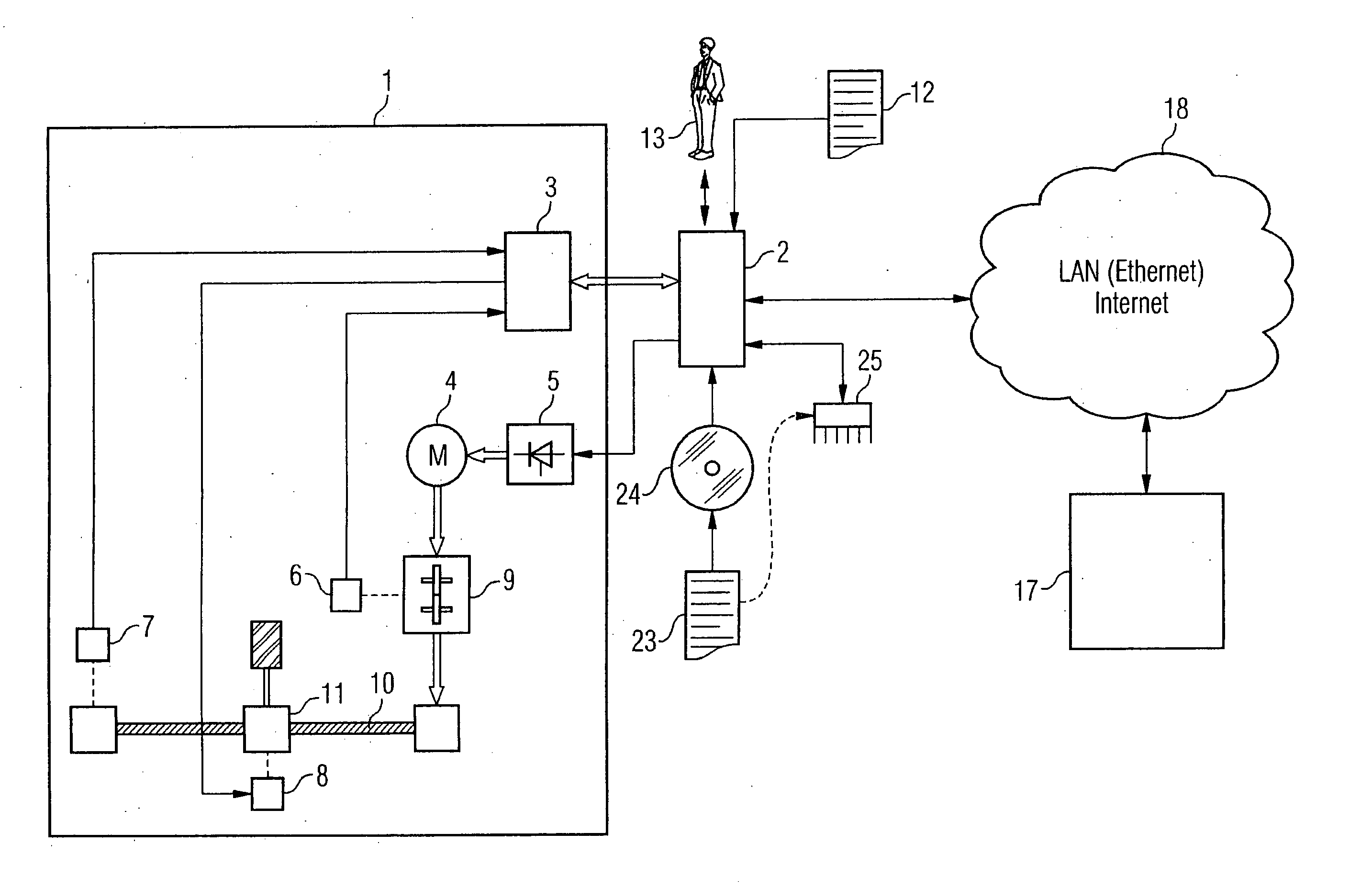
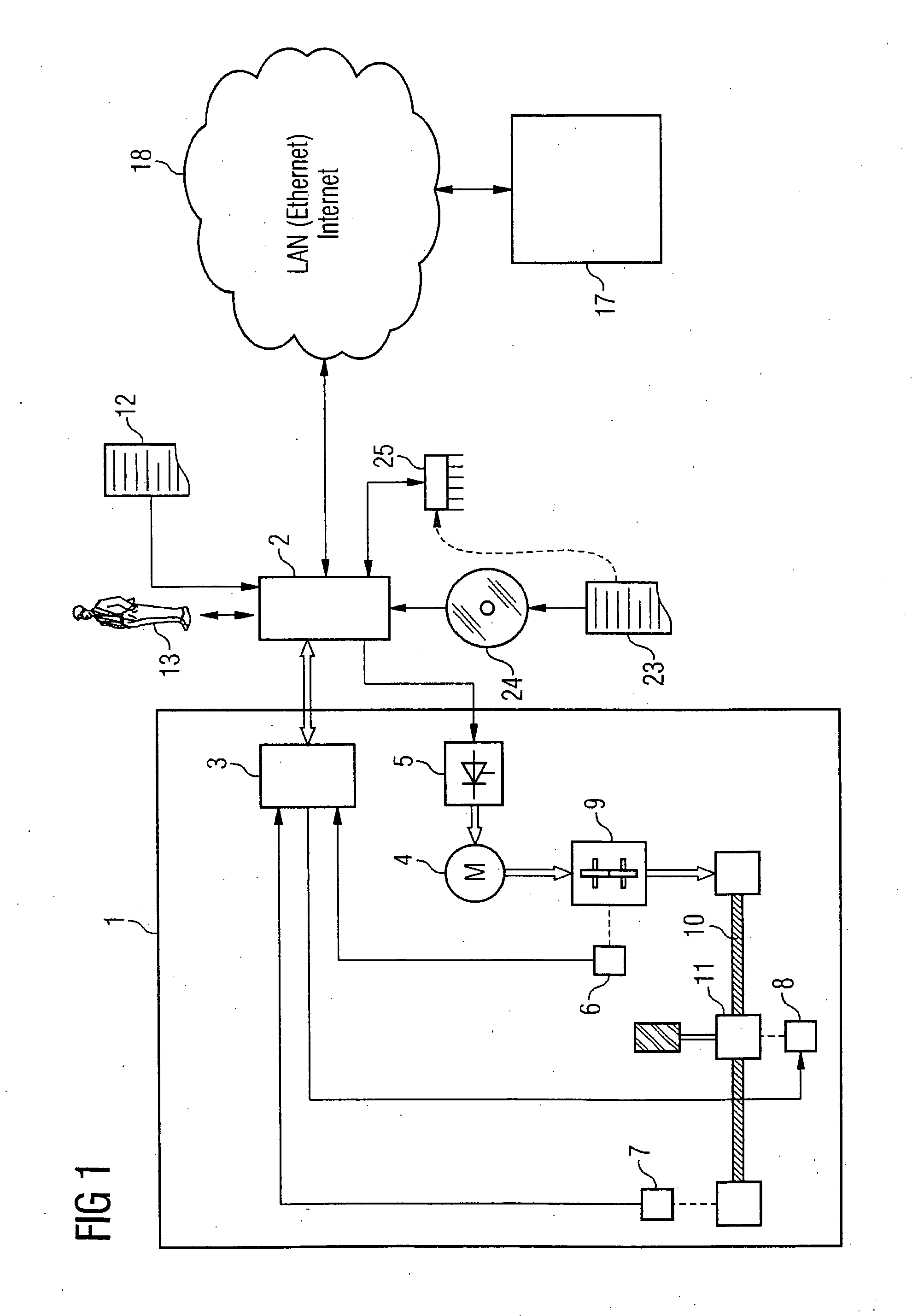
[0020] Turning now to the drawing, and in particular to FIG. 1, there is shown a controller 2 associated with a machine tool 1, for example a production machine 1. The exemplary controller 2 can be, for example, a numerical controller 2. Alternatively, the controller 2 of the production machine 1 can also be a stored-memory controller.

[0021] The machine tool 1 can also incl...


PUM


Abstract

A production machine has a controller and a plurality of components that include link addresses associated with a memory region of a separate computer that can be connected with the controller via a computer-to-computer link. Parameter data for the components are stored in the memory region. The link addresses are stored either in the components themselves or in component associated with these components. The controller accesses the link addresses and then uses the link addresses to access parameter data. The controller executes a control program to determine control commands for components, such as actuators, of the production machine, with the control commands depending on the parameter data, and transmits the control commands to the production machine.

Description

CROSS-REFERENCES TO RELATED APPLICATIONS [0001] This application claims the priority of German Patent Application, Serial No. 103 47 972.4, filed Oct. 15, 2003, pursuant to 35 U.S.C. 119(a)-(d), the disclosure of which is incorporated herein by reference. BACKGROUND OF THE INVENTION [0002] The present invention relates to a method for controlling a production machine, in particular a machine tool, with a controller associated with a production machine. The present invention is also directed to a data carrier with a computer program for carrying out the method and a controller for a production machine, in particular a machine tool, with a program memory storing a computer program that can be executed by the controller to perform the method. The present invention is further directed to a production machine, in particular a machine tool, with an associated controller and a plurality of components, wherein the controller is configured to execute the method. [0003] Nothing in the followi...

Claims


Application Information

Patent Timeline
IPC IPC(8): G05B19/042G05B19/05G05B19/418
CPCG05B19/0426G05B19/41845G05B19/056Y02P90/02Y02P90/80
Inventor DOLANSKY, STEFAN
Owner SIEMENS AG
Why Eureka
Eureka Blog
Learn More