Eureka AIR delivers breakthrough ideas for toughest innovation challenges, trusted by R&D personnel around the world.

Method for medical imaging and a medical imaging system

Inactive Publication Date: 2006-10-26
SIEMENS AG
View PDF8 Cites 9 Cited by
  • Summary
  • Abstract
  • Description
  • Claims
  • Application Information

AI Technical Summary

Benefits of technology

[0013] By means of a combination of at least two of the imaging systems, mutually supplementary image information is obtained in a particularly advantageous manner, so that the medical personnel engaged in the examination are provided with more, and also more accurate, information on the vessel and / or organ to be examined, and within a uniform system.
[0014] In particular, the combined use of blood-permeable light and tissue-permeable light offers substantial advantages. For example, in just one examination it is possible to reliably, and comparatively quickly, search the tissue surfaces of vessels or organs for possible problem areas with the aid of the blood-permeable methods. If suspicious areas are detected, these can be examined more closely at the same time. In particular, the tissue can be examined in depth using the tissue-permeable OCT. Especially the combination of these imaging methods within an overall system, with only one catheter having to be introduced, enables a more precise and reliable result compared with the conventional simple examination methods.
[0017] Preferably, particularly in addition to the axial irradiation of the tissue to be examined with the axial optical fiber or with the optical fiber bundle, a radial irradiation is provided. For this purpose the optical fiber cable includes a radial optical fiber that has a light exit aperture directed radially relative to the longitudinal direction of the catheter. In this case, the radial optical fiber is appropriately rotatable about the longitudinal axis of the catheter. In particular, the combination of axial light propagation and radial light propagation enables concealed structures to be examined and detected, that are not detected simply by an axial “direction of view”. Because they are located, for example, in the shaded area behind obstacles, the concealed structures cannot be detected by axially emerging light. Further advancement of the catheter with a succeeding radial irradiation is required to obtain an image of the concealed structures.
[0019] In a preferred embodiment, the catheter is moved during the examination within the vessel or organ so that it takes up different positions. Image information is acquired at the different positions of the catheter, from which a three-dimensional image data record is generated. Three-dimensional images of the anatomy of a vessel or organ that are reliable and easy to evaluate are obtained in this way.
[0022] Preferably, the image data obtained using the intravascular catheter system is additionally compared with the image data from other imaging non-intravascular systems and combined as required. Such further imaging systems are, for example, computer tomography, magnetic resonance examination, 3D or 2D angiography or the extravascular ultrasound examination. By means of a combination with these other imaging systems, information that is therefore reliable and comprehensive is obtained regarding the vessels or organs examined.

Problems solved by technology

The problem with the chosen wavelength of 1300 nm is that blood is not permeable to IR light, because the light is scattered at a phase boundary between blood plasma and blood cells.

Method used


Image

  • Method for medical imaging and a medical imaging system
  • Method for medical imaging and a medical imaging system
  • Method for medical imaging and a medical imaging system

Examples


Embodiment Construction

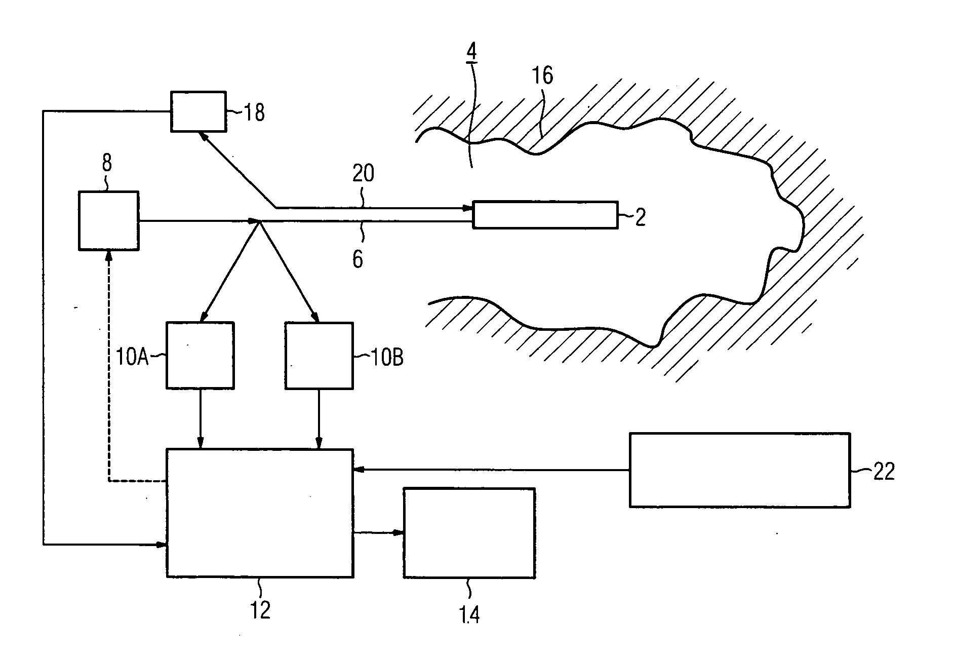
[0031] A medical imaging system shown in FIG. 1 has a catheter 2 that during the examination is inserted into the vessel to be examined 4 of a human body. The catheter 2 is connected via an optical fiber cable 6 to a supply unit 8. Infrared light is supplied to the optical fiber cable 6 via this supply unit. The supply unit 8 is designed so that it can supply infrared light both in the 1300 nm wavelength range and also approximately in the 1800 nm wavelength range.

[0032] The imaging system also includes a first reception and evaluation unit 10A, that is designed for imaging using the optical coherence tomography (OCT) imaging method. Furthermore, the system has a second reception and evaluation unit 10B, that is designed as an infrared camera for radio-optic imaging. The evaluation units process received light signals to obtain image information that is transmitted to a central computer unit 12. In the computer unit 12, this image information is further processed and displayed for ...


PUM


Abstract

To improve medical imaging with the aid of an intravascular catheter, an area to be examined is irradiated with the infrared light and an assigned scatter light signal is processed to form an image. To do this, OCT imaging with the aid of tissue-permeable light at a wavelength of approximately 1300 nm is combined with OCT imaging with the aid of blood-permeable light at a wavelength of approximately 1800 nm and / or with radio-optic imaging with the aid of an infrared camera (10B) with blood-permeable light at a wavelength of 1800 nm. This combined imaging catheter system opens up new and improved application possibilities in the medical field and the quality of the images received can be improved by the mutual correction of the particular image data.

Description

CROSS REFERENCE TO RELATED APPLICATIONS [0001] This application claims priority to the German Application No. 10 2005 012 699.5, filed Mar. 18, 2005 which is incorporated by reference herein in its entirety. FIELD OF INVENTION [0002] The invention relates to a method of medical imaging and a medical imaging system for recording intravascular images. BACKGROUND OF INVENTION [0003] Images of the area of the vessels or organs of interest mainly using intravascular imaging systems are created for the medical treatment of vessels or organs of the human body. With this method, a catheter is normally introduced into the human body. An optical fiber cable is arranged within the catheter for optical imaging methods. The area to be examined is irradiated with infrared (IR) light. The light is reflected or scattered and applied to an evaluation unit as a light signal. SUMMARY OF INVENTION [0004] A common method in this case is, for example, the optical coherence tomography (OCT) method. With t...

Claims


Application Information

Patent Timeline
IPC IPC(8): A61B6/00
CPCA61B5/6852A61B5/0066
Inventor BOESE, JANKLEEN, MARTINRAHN, NORBERT
Owner SIEMENS AG
Why Eureka
Eureka Blog
Learn More