Multi-network exchange system for telephony applications

a multi-network exchange and application technology, applied in the field of communication systems and methods, can solve the problems of inability to receive calls, inability to offer the kind of features that are available, and ineffective pstn system,

Inactive Publication Date: 2005-04-28
EMERJ
View PDF27 Cites 211 Cited by
  • Summary
  • Abstract
  • Description
  • Claims
  • Application Information

AI Technical Summary

Benefits of technology

[0027] U.S. patent application 2002 / 0118671 (Staples, et al.) Aug. 29, 2002 illustrates a communication system that extends office telephony and network data services to remote clients through the Internet. The system has a telephony server, a local area network, a server system, and a user communication device. The telephony server (e.g. a Private Branch Exchange) provides telephony services for a plurality of office lines. The local area network couples to the Internet. The telephony server and local area network may reside within an office environment. The server system couples to the telephony server and to the local area network. The user communication device establishes a first connection to the server system through the Internet. In response to the first connection, the server system automatically provides access for the user communication device to the telephony server. Also, the server system automatically invokes a call forwarding operation in response to the first connection, so that subsequent telephone calls, intended to reach the user's office line, are forwarded to the server system. When the server system receives a first telephone call, which has been redirected by the telephony server from the user's office line, the server system forwards the first telephone call to the user communication device through the first connection. The user communication device may also establish a secure data connection to the server system through the Internet. The secure data connection provides the remote user with access to the local area network in a manner which protects the data security of the local area network.
[0028]“A Flexible, Module-Based Soc-Approach for Low-Power VoIP-Applications” Fugger, et al., 15th Annual IEEE International ASIC / SOC Conference, 2002, pp.: 256-260, September 2002 describes a system on chip (SoC) that is suitable for both conventional telephony via the public switched telephone network (PSTN) and voice over Internet protocol (VoIP). A highly flexible approach offers the possibility to integrate several interface types, customizable by software download. Additional download capabilities facilitate the integration of voice-codecs for voice compression, algorithms for silent noise injection, far end line echo cancellation, and fax / modem termination.

Problems solved by technology

The PSTN system, however, is not cost effective and does not offer the kind of features that are available when using a digital communication network such as the Internet.
Even though this is a more attractive solution compared to the software only solution but it still suffers from the fact that the user requires a computer 35 to place a telephone call.
The main problem in this type of approach is the relatively long connection time, the inability to receive calls (the unit is not online at all times) and the undesirable extra modem delay.
The main issue here is the addressing scheme.
The other problem stems from the fact that VoIP capability is only available for the telephone set, but not the landline.
These solutions do not take advantage of the features provided by digital networks such as the Internet.
This inability originates from the fact that the existing IP solutions do not translate the PSTN attributes to the digital network and vice versa.

Method used


Image

  • Multi-network exchange system for telephony applications
  • Multi-network exchange system for telephony applications
  • Multi-network exchange system for telephony applications

Examples


Embodiment Construction

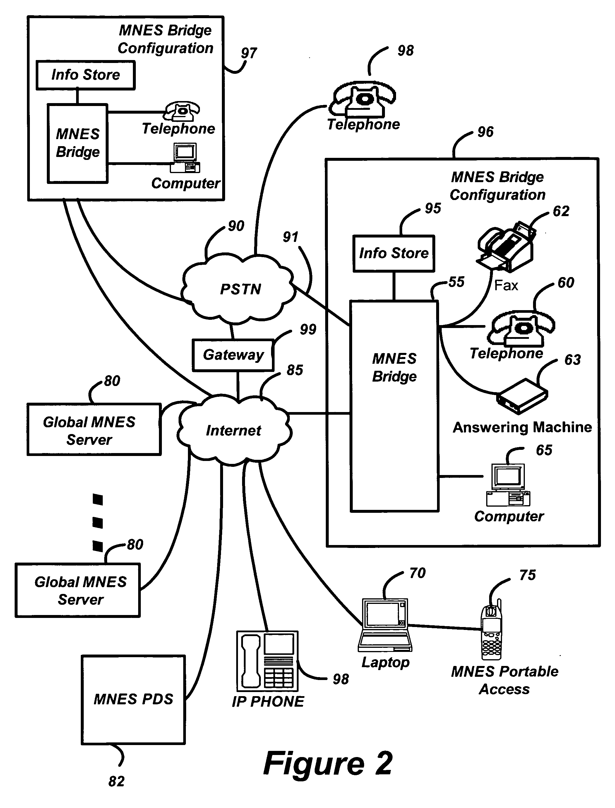
[0082] Refer now to FIG. 2 for a detailed description of the operation of the Multi-Network Exchange System (MNES) of this invention. The Multi-Network Exchange System includes one or more MNES bridges 55 and 97 that allow information in the form of voice or fax telephone calls to be exchanged between a PSTN network 90 and a digital communications network 85 such as the internet. The MNES bridge 55 has a telephone interface to the PSTN network 90 and a digital network interface for communications the internet 85. At least one telephone set 60 is connected to the MNES bridge 55 and at least one computer system 65 is similarly connected to the MNES bridge 55. Optionally, a facsimile machine (fax) 62 and an answering machine 63 may be connected to the MNES bridge 55 (while not shown the fax machine 62 and answering machine 63 may be connected to the other MNES Bridge 97) During normal operation, the PSTN network 90 communicates telephone calls directly to the telephone set 60 and the i...


PUM


Abstract

A multi-network exchange system has a first type network (PSTN) and a second type network (Internet) and a multi-network exchange bridge in communication with the first and second type networks for the transfer of electronic information signals (telephone calls) between the first and second type networks. The multi-network exchange bridge apparatus facilitates transfer of electronic information signals to a portable access device or a gateway portal in communication with a node of one of second type networks from the first network. The multi-network exchange bridge has at least one multi-network instantiation device that enables the portable access device to function as a remote extension of the multi-network exchange bridge. A fixed address translation device provides conversion of a first address fixedly describing a node of the first type network to a second address or third address virtually describing nodes of the second type network

Description

BACKGROUND OF THE INVENTION [0001] This application claims priority to U.S. Provisional Patent Application Ser. No. 60 / 513,814, Filing Date Oct. 23, 2003, which is herein incorporated by reference. [0002] 1. Field of the Invention [0003] This invention relates generally to a communications systems and methods. More particularly, this invention relates to systems and methods for bridging between types of communications networks. Even more particularly, this invention relates to systems and methods for bridging between a public switched telephone network and a packet switched digital communications network such as the Internet. [0004] 2. Description of Related Art [0005] Referring to FIG. 1, the Public Switched Telephone Network (PSTN) 5, as is known in the art, provides an extremely reliable system that has been available for more than a century. It is simple to operate and is used at home and office where telephone sets 10 are connected directly to the PSTN network for communication...

Claims


Application Information

Patent Timeline
Patent Type & Authority Applications(United States)
IPC IPC(8): G06F15/16H04L29/06H04M7/00
CPCH04L29/06027H04M7/0057H04M7/0069H04L65/103H04L65/104H04L65/1006H04M2207/20H04L65/1104H04L65/1101
Inventor VAZIRI, FARAMARZGRAEFE, HERBERT R.WANG, XINPLETCH, ANDREWPALGE, JEFFREY H.
Owner EMERJ
Why Eureka
Try Eureka