
Refrigeration system with a plate-type condenser and method for compacting it

a refrigeration system and condenser technology, applied in refrigeration machines, domestic cooling devices, lighting and heating devices, etc., can solve the problems of increasing the transportation cost of the refrigeration system from one place, the system is more difficult to move, etc., to achieve the effect of reducing the position of the evaporator coil, facilitating and facilitating both the handling

Inactive Publication Date: 2005-05-05
EMPRESA BRASILEIRA DE COMPRESSORES SA (EMBRACO)
View PDF4 Cites 3 Cited by
  • Summary
  • Abstract
  • Description
  • Claims
  • Application Information

AI Technical Summary

Benefits of technology

"The invention is a refrigeration system that includes a compressor, evaporator coil, and condenser. The condenser is a plate type, with a lower and upper section that lie on the same vertical plane. The evaporator coil is positioned above the upper plate section of the condenser and receives refrigerant fluid through a capillary tube extending from the lower part of the lower plate section to the evaporator coil. A suction tube extends from the evaporator coil along the height of the lower and upper plate sections of the condenser and back to the compressor for admission of the refrigerant fluid. The capillary tube and suction tube are made of a material that allows bending, which allows for a compact form of the refrigeration system for easier handling and transportation. When the system is mounted in a refrigeration appliance, the upper plate section is bent back to its original position and the suction tube and capillary tube are straightened to elevate the evaporator coil and arrange all components in an adequate position for mounting in the appliance. The technical effect of the invention is to reduce the overall dimension of the refrigeration system, making it easier to handle and transport and more efficient in terms of cost."

Problems solved by technology

When the refrigeration system is of the type that has a plate-type condenser, a practical problem appears, resulting from the fact that the dimension of the condenser is relatively large, making the transportation of the system more difficult and increasing the transportation costs of the refrigeration system from one place to the other.

Method used


Image

  • Refrigeration system with a plate-type condenser and method for compacting it
  • Refrigeration system with a plate-type condenser and method for compacting it
  • Refrigeration system with a plate-type condenser and method for compacting it

Examples


Embodiment Construction

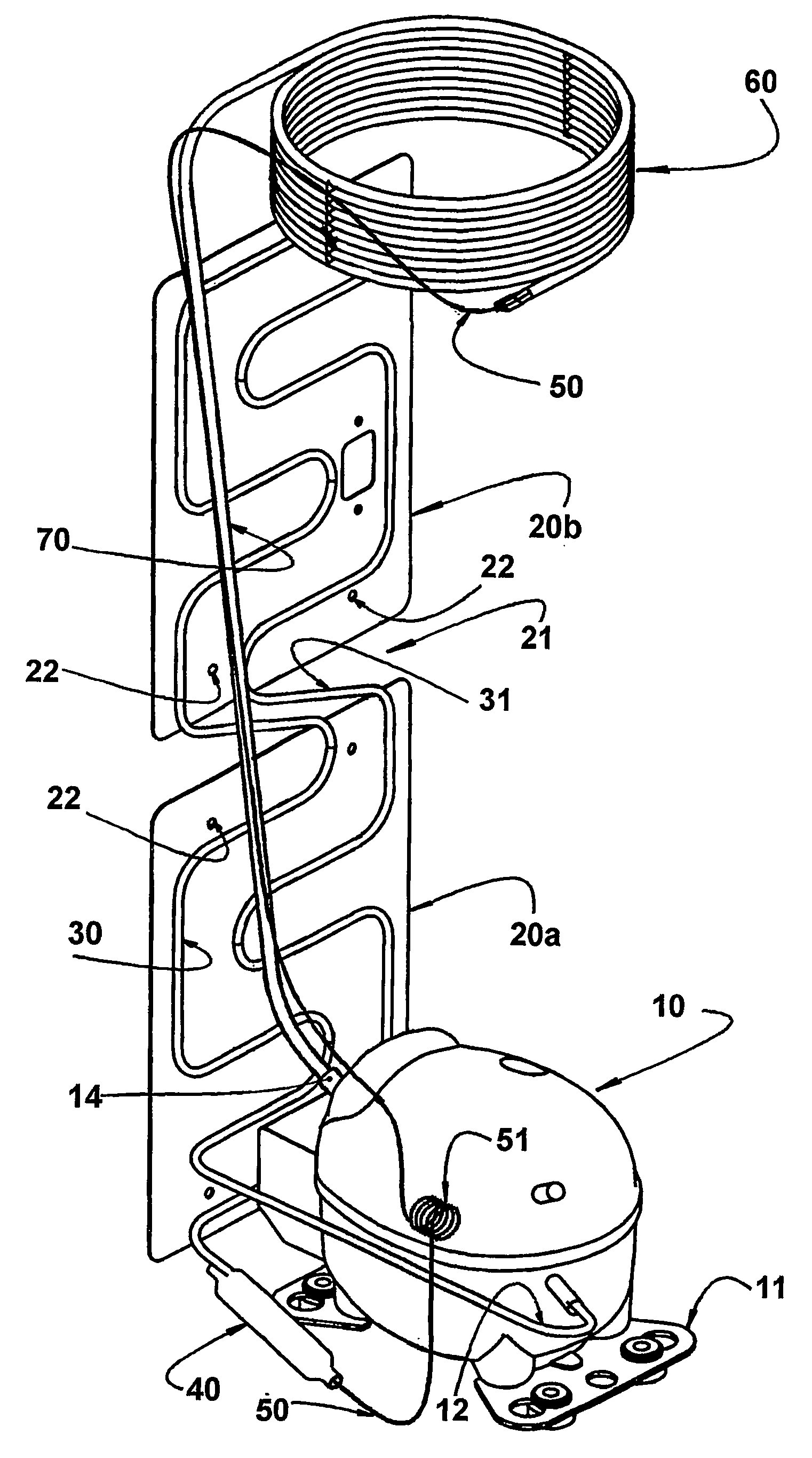
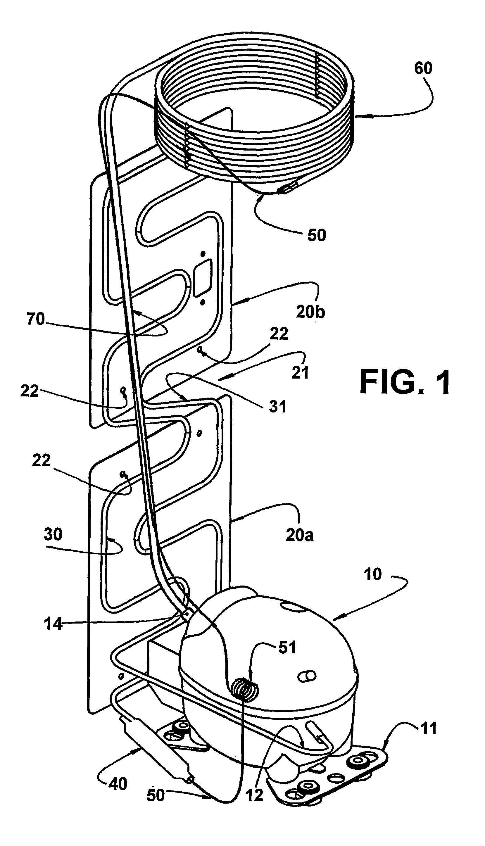
[0017]FIG. 1 shows a refrigeration system having the usual conventional components, but with a plate-type condenser constructed according to the invention. The refrigeration system is shown with a general arrangement of its components being positioned in the form they are designed to be mounted in the cabinet of a refrigeration appliance (not illustrated), and which also represents the final form after the manufacturing steps and test procedures. When mounted in the cabinet of the refrigeration appliance, the several components are supported by the adequate structural mounting members.

[0018] The system presents, at the bottom thereof, a compressor with a conventional construction mounted in a hermetic shell 10, which presents a mounting support 11, through which the hermetic shell 10 is mounted in the cabinet of the refrigeration appliance. The compressor compresses a high-pressure refrigerant fluid, which is supplied to a discharge tube 12 mounted to the hermetic shell 10 and whic...


PUM


Abstract

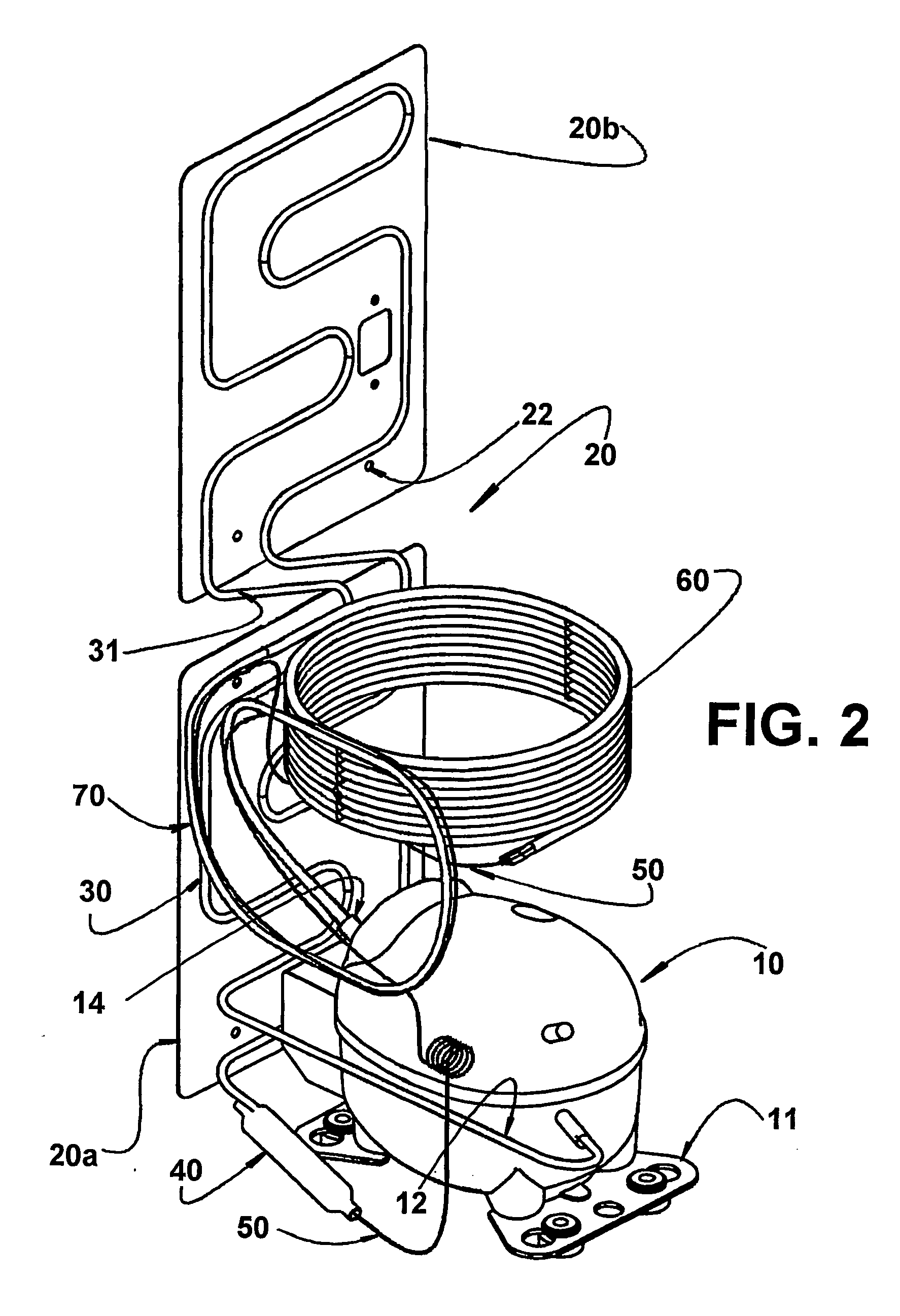
A refrigeration system with a plate-type condenser and a method for compacting it, to be applied to a refrigeration appliance presenting a compressor mounted in a hermetic shell (10), an evaporator coil (60), and a plate-type condenser (20). The refrigerant fluid coming from the compressor is supplied to a condenser tube (30), which is formed on a lower plate section (20a) and on an upper plate section (20b) of the condenser (20) and extends from the bottom to the top and back to the bottom. After manufacture, the lower plate section (20a) and the upper plate section (20b) are placed one over the other, the evaporator coil (60) is positioned by a suction tube (70) connected to the compressor.

Description

FIELD OF THE INVENTION [0001] The present invention refers to a refrigeration system, which includes a plate-type condenser manufactured in different sections, in order to make the system more compact for handling and shipping. The present invention further refers to a method to make said system more compact. PRIOR ART [0002] Refrigeration systems formed by a compressor, an evaporator, a condenser, and other necessary components are well known. Such systems are used in several types of appliances for commercial and residential use, such as refrigerators, freezers, air-conditioners, and other cooling devices. Most refrigeration systems usually work, compressing a refrigerant fluid in the vapor state in a compressor, said refrigerant fluid subsequently transferring the heat to an external environment through a condenser, returning to the liquid state. The refrigerant fluid in the liquid state passes through an expansion device and, immediately after, in an evaporator, returning to the...

Claims


Application Information

Patent Timeline
Patent Type & Authority Applications(United States)
IPC IPC(8): F25D19/00
CPCF25D2400/32F25D19/00
Inventor PEREIRA, ROBERTO HORNVOLLRATH, INGWALD
Owner EMPRESA BRASILEIRA DE COMPRESSORES SA (EMBRACO)
Learn More