Method and clamp for moulding surface positioning clamping of finish forge blade

A technology for positioning and clamping and blades, which is applied in the direction of positioning devices, clamping, and manufacturing tools, can solve problems such as blade deformation or damage, and achieve the effects of reduced processing time, good fluidity, and increased rigidity

Active Publication Date: 2012-11-14
AECC AVIATION POWER CO LTD
View PDF5 Cites 43 Cited by
  • Summary
  • Abstract
  • Description
  • Claims
  • Application Information

AI Technical Summary

Problems solved by technology

[0005] In order to overcome the deficiencies in the prior art that blades are prone to deformation or damage, the present invention proposes a method for positioning and clamping precision forging blade profiles and its fixtures

Method used


Image

  • Method and clamp for moulding surface positioning clamping of finish forge blade
  • Method and clamp for moulding surface positioning clamping of finish forge blade
  • Method and clamp for moulding surface positioning clamping of finish forge blade

Examples


Embodiment 1

[0049] This embodiment is a method for positioning and clamping of the precision forging blade profile. The specific process is:

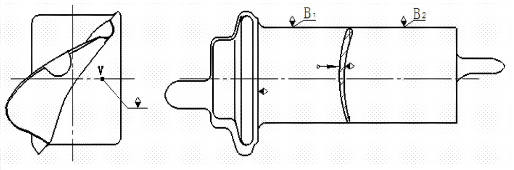
[0050] Step 1, pretreatment of the glued surface. On the blade pot profile positioning block and blade back profile clamping block of the fixture, a profile that is offset from 2 to 2.5mm outwards along the normal direction of the theoretical profile thickness is processed, and the profile surface that needs to be glued Napped.

[0051] Step 2, apply glue. Coat TS355 high-precision positioning glue on the surface of the leaf pot profile positioning block and leaf back profile clamping block of the fixture, and cure for 24 hours at room temperature. The coating thickness of the high-precision positioning glue is 3.5-4.5 mm. After the high-precision positioning glue is bonded and solidified with the blade basin profile positioning block and the blade back profile clamping block, the high-precision positioning glue coated on the jaws is processed to the...

Embodiment 2

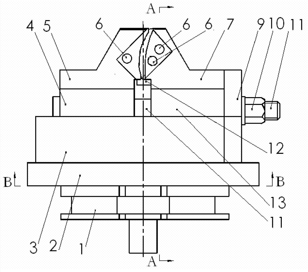
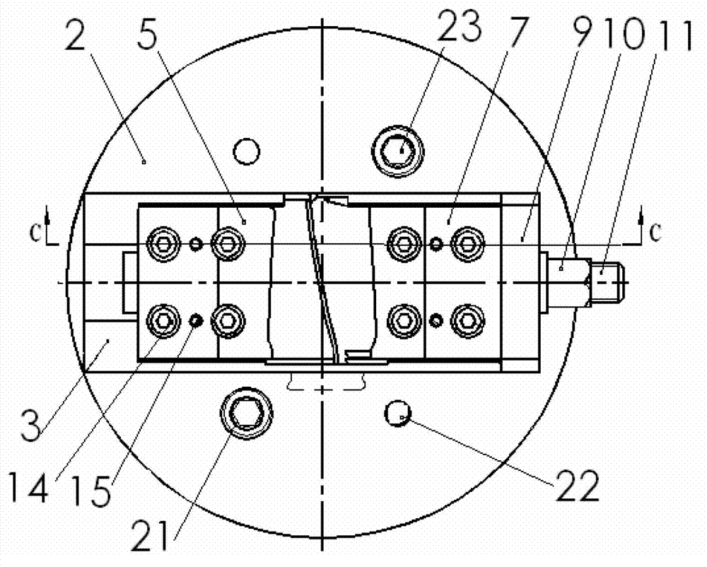
[0056] This embodiment is a clamp for positioning and clamping the blade profile for precision forging. Said clamp adopts a vise structure, including tray 1, bottom plate 2, guide rail 3, clamping guide block 4, leaf back profile clamping block 5, edge plate positioning pin 6, leaf basin profile positioning block 7, positioning Pin hole 8, baffle 9, clamping nut 10, tension rod 11, air inlet positioning pin 12, limit block 13, cylindrical pin 15, limit pin 16, guide plate 17, spring 18 and compression screw 19 .

[0057] Such as image 3 As shown, the pallet 1 is the connection between this embodiment and the machine tool. A bottom plate 2 is installed on the upper surface of the tray 1. The guide rail 3 is horizontally installed at the center of the upper surface of the bottom plate 2, and the longitudinal center line of the guide rail 3 is perpendicular to the machine tool spindle; the guide rail groove of the guide rail 3 is a T-shaped groove. The clamping guide block 4 is ...


PUM


Abstract

The invention relates to a method and a clamp for moulding surface positioning clamping of a finish forge blade. According to the method, a vane is subjected to positioning clamping through a basin mounding surface of the blade, an inner side moulding surface of a blade root marginal plate, and a V point on the inner side mounting surface of the blade root marginal plate, by the positioning of an air inlet edge, and the clamping of a back mounding surface of the blade, as well as by using a high-accuracy positioning adhesive, and an adhesive coating method, and through a positioning block of the basin moulding surface of the blade and a clamping block of the back moulding surface of the blade. According to the method and the clamp, a satisfying contact area can be obtained by adoption of the high-accuracy adhesive, and the positioning rigidity of the blade is enhanced by adoption of the basin moulding surface of the blade, the inner side moulding surface of the blade root marginal plate and the V point on the inner side moulding surface of the blade root marginal plate for the positioning. According to the method and the device, the problems that the accurate positioning is difficult to realize and the moulding surface of the blade deforms or is damaged because the blade is thin, the blade body is small and the moulding surface is complex are solved. By the method and the device, the positioning accuracy of the mechanical processing of the blade is improved, and the technological process is optimized, so that the processing quality and the production efficiency of the blade are improved, the process is simple, the number of fixtures is reduced, the processing cycle is shortened, and the production cost is reduced.

Description

Technical field [0001] The invention is used for the machining of precision forged blades of aviation engines. Background technique [0002] At present, the positioning and clamping of domestic aero-engine precision forged blade machining is due to the lack of margin on the blade body profile and the inner profile of the edge plate, the blade body is small, the blade is thin, and the profile is complex. It is not easy to accurately locate and easily cause the blade profile. Deformation or damage, often use low melting point alloy casting box positioning method. This method converts the coordinate datum formed after precision forging of the blade into a plane datum, and then performs mechanical processing to ensure the relative twist and offset of the tenon and the blade profile. Because the blade wool tolerance occupies part of the design tolerance, there is a conversion between the blade positioning datum and the pouring box positioning datum, which occupies part of the blade m...

Claims


Application Information

Patent Timeline
Patent Type & Authority Applications(China)
IPC IPC(8): B23Q3/00
Inventor 刘秀梅刘智武张武刚余杰赵赟陈琦
Owner AECC AVIATION POWER CO LTD
Why Eureka
Try Eureka