Scan head calibration system and method

a calibration system and scanning head technology, applied in the direction of speed/acceleration/shock measurement devices, speed/acceleration/shock testing, instruments, etc., can solve the problems of system and method currently unavailable, beam is not always directed, complete failure of welding process, etc., to reduce system errors, increase positional accuracies, and high accuracy level

Inactive Publication Date: 2010-11-18
COHERENT SINGAPORE PTE
View PDF18 Cites 46 Cited by
  • Summary
  • Abstract
  • Description
  • Claims
  • Application Information

AI Technical Summary

Benefits of technology

[0009]Solutions provided by the present invention can significantly reduce system errors and increase positional accuracies in scan vision systems and laser processing systems. Laser processin

Problems solved by technology

In an actual situation, however, the laser beam is not always directed to predetermined locations on the workpiece.
This may be due to the system errors and/or installation tolerances of the laser positioning mechanism.
Without taking these errors and/or tolerances into consideration, laser beam may be directed at undesired positions on the workpiece

Method used


Image

  • Scan head calibration system and method
  • Scan head calibration system and method
  • Scan head calibration system and method

Examples


Embodiment Construction

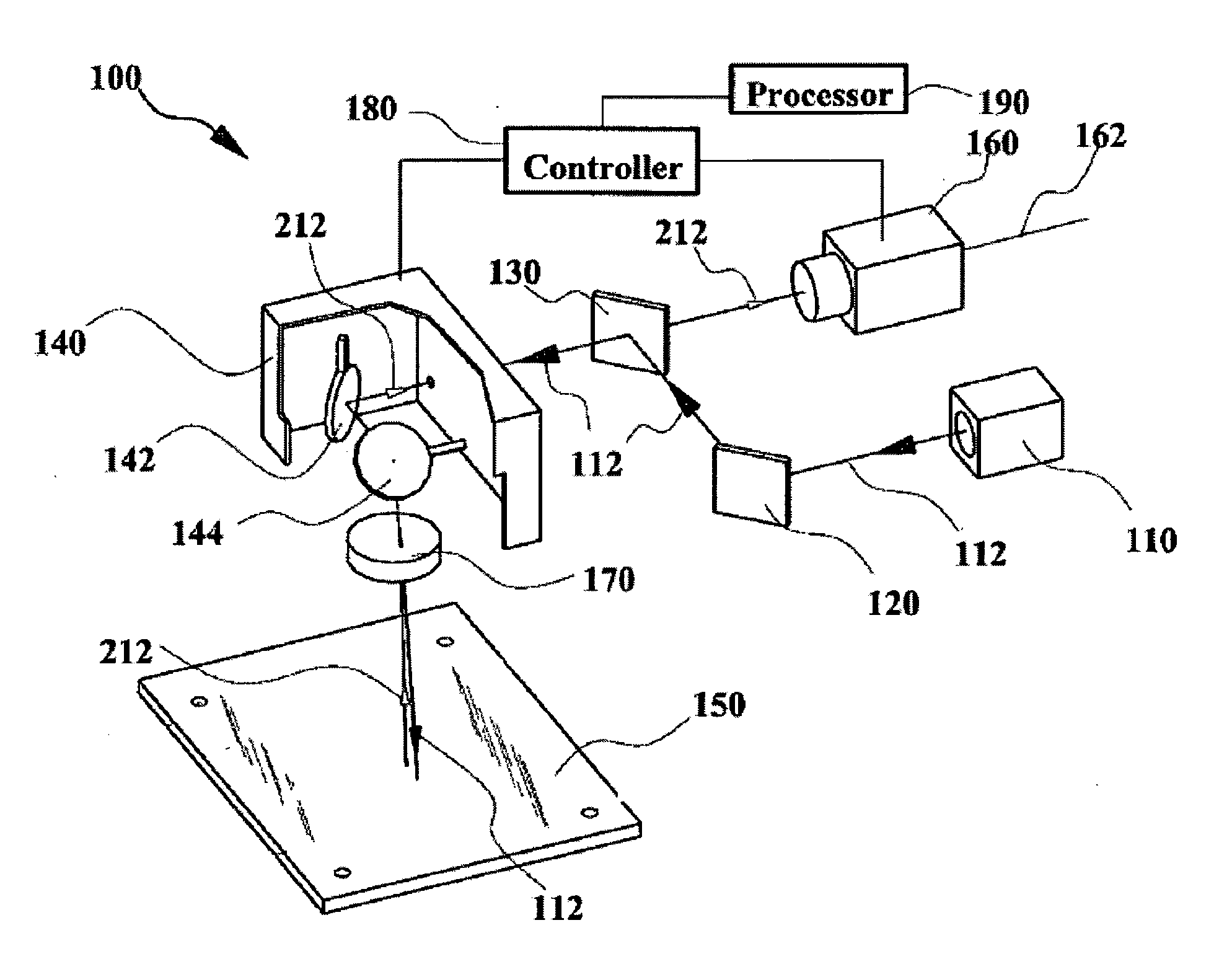
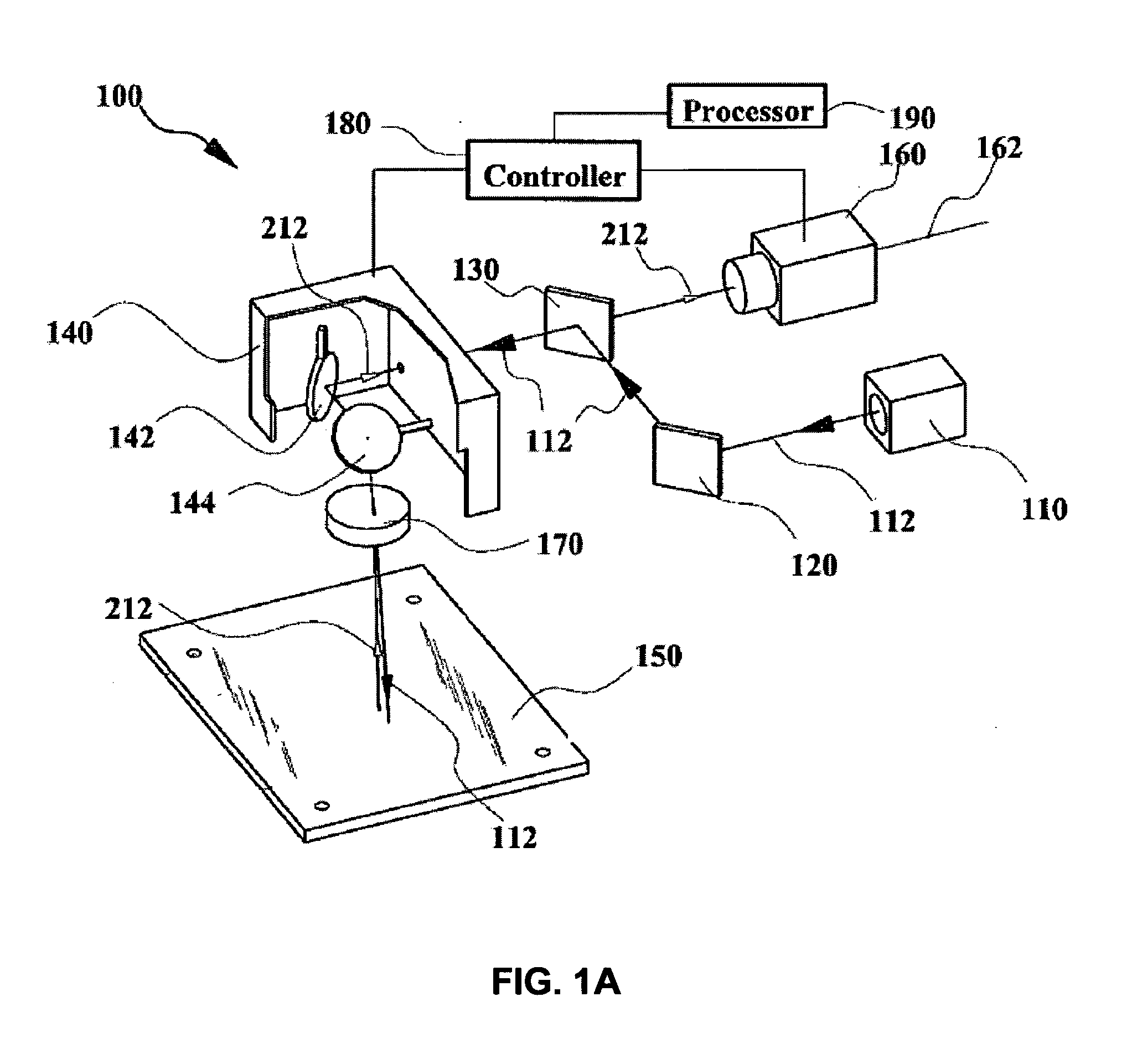
[0027]For the purpose of illustration, embodiments of the present invention will be described to a system and a method suitable for laser processing at high positional accuracy, which may be described with respect to the reduction and / or compensation of system errors for precisely positioning a laser beam onto a workpiece for laser processing.

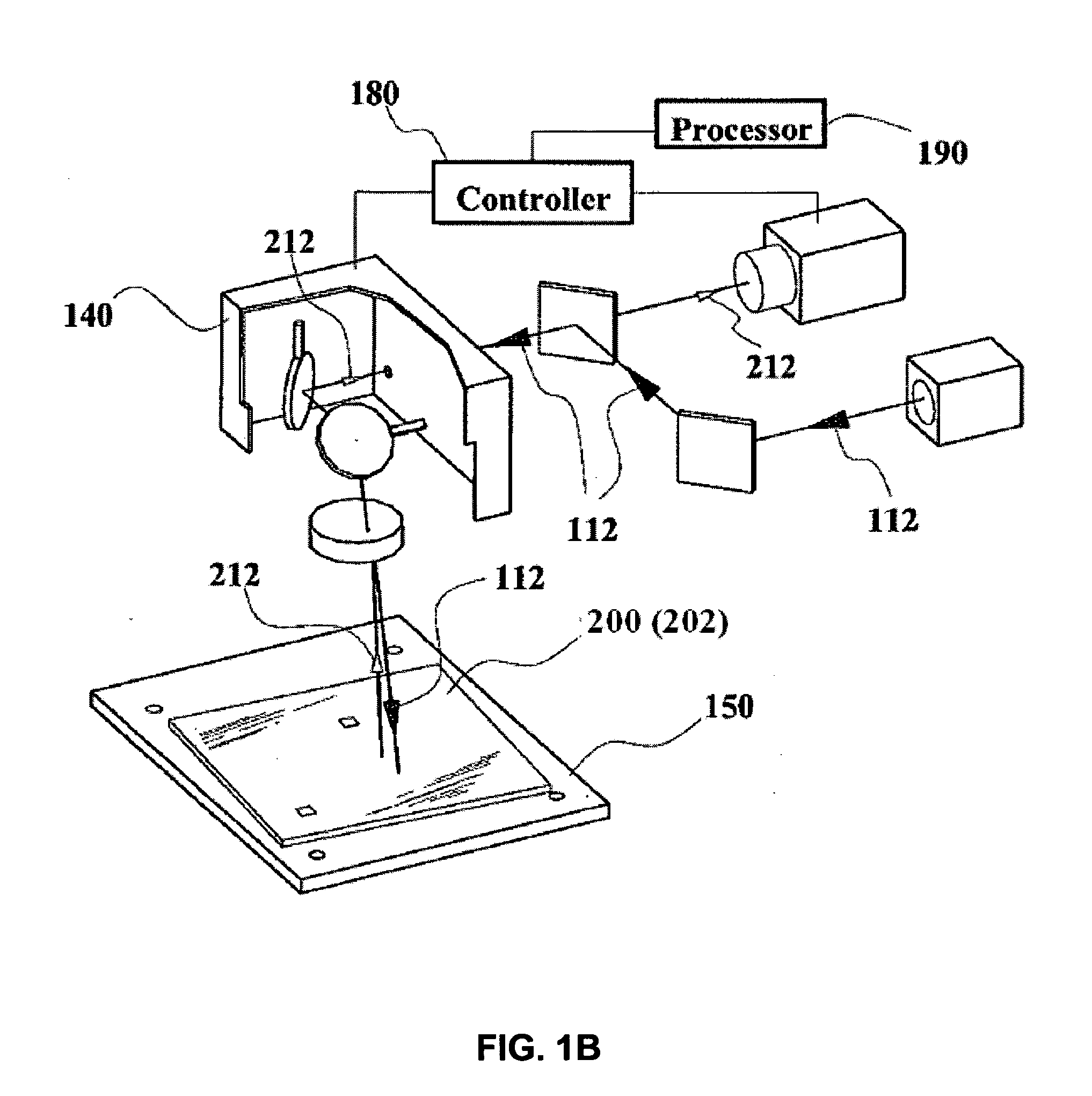
[0028]FIG. 1A shows a laser processing system 100 for processing a workpiece, for example to mark the workpiece or weld the workpiece, according to one embodiment of the present invention. FIG. 1B shows the system of FIG. 1A and having a calibration jig placed thereon for vision assembly calibration, or a workpiece placed thereon for processing.

[0029]FIG. 2 shows a scan vision system 102, according to one embodiment of the present invention. Scan vision system 102 may be used as an independent system for vision detection, optical inspection and / or precision measurement. Alternatively, vision system 102 may also be used as a scan vision assembly...


PUM

PropertyMeasurementUnit
Erroraaaaaaaaaa

Abstract

A method and system are provided for reducing a positioning error for positioning a light beam either onto or from a workpiece. A calibration mark is provided, and an image of the calibration mark is captured, to compare with a guide mark. The position of the guide mark corresponds to a set of design data or coordinates. The position of the image of the calibration mark is adjusted until the image matches with the guide mark. A set of vision compensating factors can therefore be determined. Thereafter, an image of a laser mark is captured, and adjusted to match the guide mark, to determine a set of scan head compensating factors. The design data can then be modified based on the vision compensating factors and the laser compensating factors, and used to position the laser beam onto the workpiece or capture light from a work piece to form an image.

Description

TECHNICAL FIELD[0001]The present invention relates to a Scan Head calibration system and method. In particular, it relates to a system and method for vision scanning and laser beam delivery at high positional accuracy.BACKGROUND[0002]Precision positioning of light rays such as visible light beams and / or laser beams are required in certain industrial applications, such as vision inspection and laser processing. One example is laser marking for creating visually perceptible signs at pre-defined locations of a workpiece using a laser beam. Apart from marking, laser systems can also be used in other applications such as micro-machining, surface processing, trimming, welding, and cutting, etc.[0003]In a laser marking, welding or machining process, coordinate data or parameters of the predetermined locations on a workpiece at which the process is to be carried out, are programmed into a laser beam positioning controller, with reference to a coordinate system. Under an ideal situation, the...

Claims


Application Information

Patent Timeline
IPC IPC(8): G06F19/00
CPCB23K26/041G01B21/042G01B11/03B23K26/0807B23K26/042B23K26/082
Inventor BUK, MUM FATT
Owner COHERENT SINGAPORE PTE
Why Eureka
Try Eureka