Calibration device and calibration method of position sensitive sensor

A technology of sensitive sensor and calibration device, which is applied in the direction of instruments, etc.

Active Publication Date: 2012-06-27
BEIJING GUOWANG OPTICAL TECH CO LTD
View PDF3 Cites 15 Cited by
  • Summary
  • Abstract
  • Description
  • Claims
  • Application Information

AI Technical Summary

Problems solved by technology

Right now

Method used


Image

  • Calibration device and calibration method of position sensitive sensor
  • Calibration device and calibration method of position sensitive sensor
  • Calibration device and calibration method of position sensitive sensor

Examples


Embodiment Construction

[0076] The present invention will be further described below with reference to the accompanying drawings and embodiments, but the protection scope of the present invention should not be limited by this.

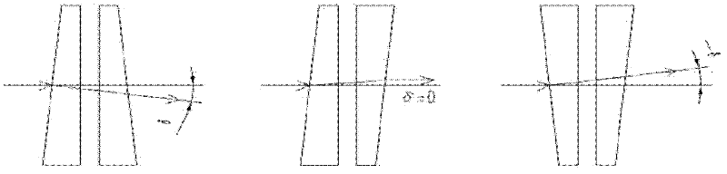
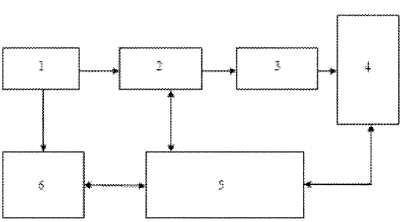
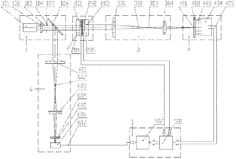
[0077] see image 3 and Figure 4 , image 3 It is a schematic diagram of the optical path of the calibration device of the position sensitive sensor of the present invention, Figure 4 Schematic diagram of the optical path for the maximum angle of beam deflection. As can be seen from the figure, the calibration device of the position sensitive sensor of the present invention includes an illumination unit 1, a double optical wedge unit 2, a pointing sensitive optical path unit 3, a position sensitive sensor 4, a data acquisition and control unit 5 and a CCD beam monitoring unit 6:

[0078] The lighting unit 1 is composed of a laser 101, a collimating mirror 102, a small aperture diaphragm 104 and a beam splitter 106. The laser light emitted by the laser 101 becomes a paral...


PUM


Abstract

The invention relates to a calibration device and a calibration method of a position sensitive sensor. The device comprises a lighting unit, a double-optical-wedge unit, a direction sensitive optical path unit, a position sensitive sensor, a data acquisition and control unit and a CCD (Charge Coupled Device) beam monitoring unit. The calibration device and calibration method of the position sensitive sensor have the advantages that the structure is simple, the operation is simple, the calibration method is accurate and reliable, and the response range, the linearity, the accuracy and the dynamic response error of the position sensitive sensor can be quickly calibrated.

Description

technical field [0001] The invention relates to a position sensor, in particular to a calibration device and a calibration method for a position sensitive sensor (Position Sensitive Detector) of a lithography machine. Background technique [0002] The calibration of the sensor is generally to check the theoretical value or the measured value of the reference instrument with the actual output value of the instrument to be calibrated. Therefore, we can calibrate the sensor as long as we have a set of theoretical values ​​or measured values ​​of standard instruments, and another set of actual measured values ​​of the sensor to be calibrated. [0003] A position sensitive sensor (Position Sensitive Detector, referred to as a position sensitive sensor) is an optoelectronic sensor sensitive to the position of the incident light spot on its photosensitive surface. When the incident light spot falls on different positions of the photosensitive surface, different electrical signals ...

Claims


Application Information

Patent Timeline
Patent Type & Authority Applications(China)
IPC IPC(8): G01D18/00
Inventor 黄立华鲍建飞杨宝喜曾爱军任冰强彭雪峰陈贝特黄惠杰
Owner BEIJING GUOWANG OPTICAL TECH CO LTD
Why Eureka
Try Eureka