Golf club head

a golf club and head technology, applied in the field of golf club head, can solve the problems of reducing the shearing strength of the bonded surface, reducing the precision requirement and fabrication cost, and increasing the separation of the striking plate from the shell

Inactive Publication Date: 2006-11-09
FUSHENG IND CO LTD
View PDF6 Cites 41 Cited by
  • Summary
  • Abstract
  • Description
  • Claims
  • Application Information

AI Technical Summary

Benefits of technology

[0008] Based on the aforementioned, the purpose of the present invention is to provid...

Problems solved by technology

The conventional manufacturing of the golf club head, due to limitations based upon the differences in the metallic materials of the shell and the striking plate, are mostly using the brazing method for bonding the shell and the striking plate.
Although the brazing bonded golf club head possesses base plate structural strength; nevertheless, the bonded surface's shearing strength is poorer.
Therefore, after a multitude of ball strikes, the bonding portion between the shell and the striking plate exhibits cracks, which eventually leads to the separation of the striking plate from the shel...

Method used


Image

  • Golf club head
  • Golf club head
  • Golf club head

Examples


first embodiment

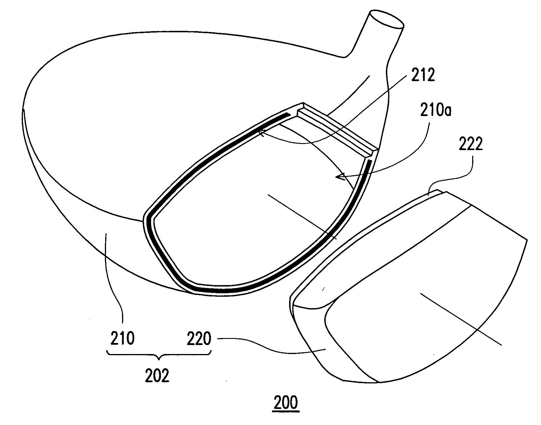
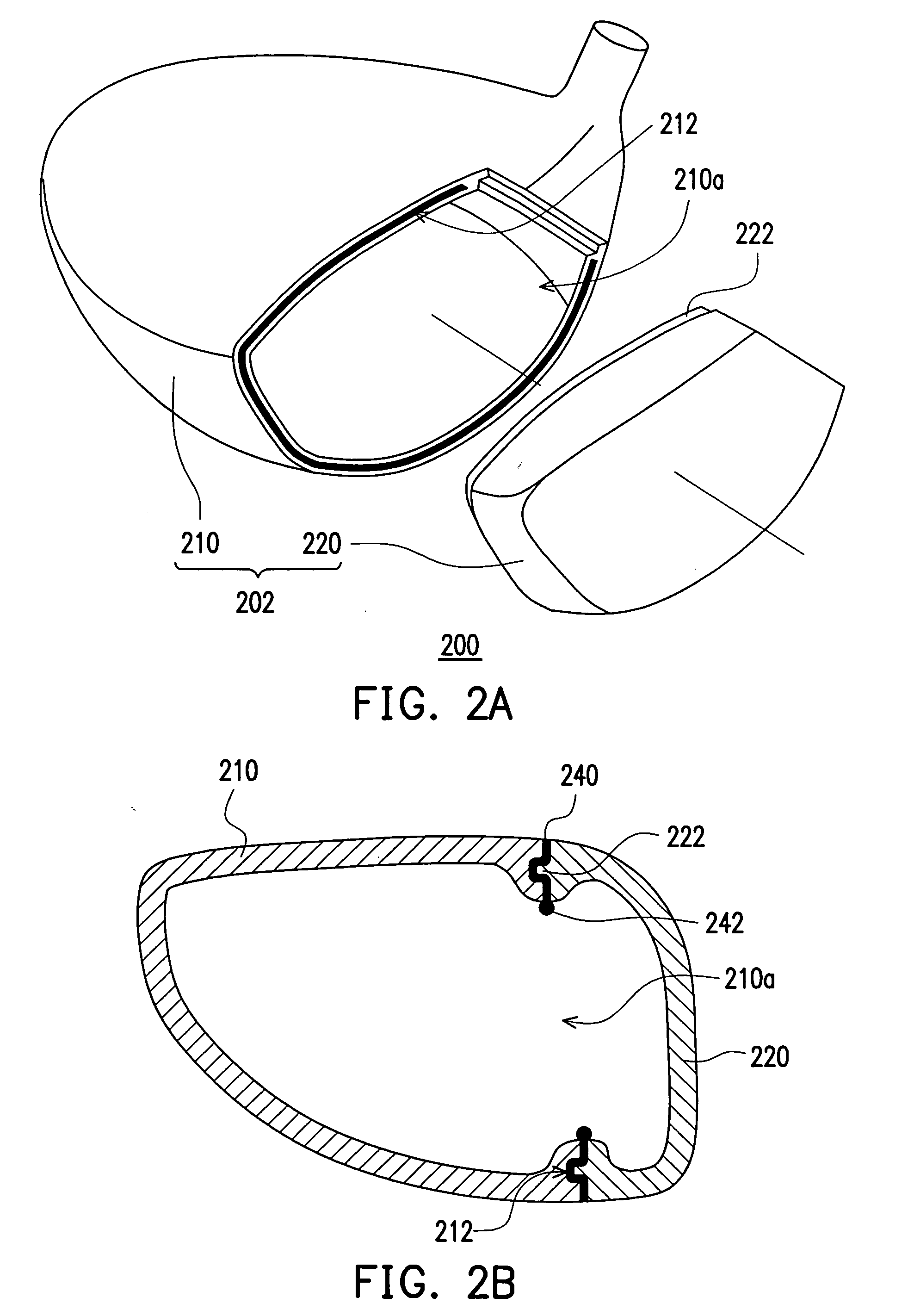
[0024] A three dimensional exploded view and a cross-sectional view of a first embodiment of the present invention respectively illustrates a golf club head, as in FIG. 2A and FIG. 2B. As illustrated in FIG. 2A and FIG. 2B, the golf club head 200 has a club head body 202, in which the club head body 202 is mainly formed from a shell 210 and a striking plate 220. In the present embodiment, the club head body 202 can be, for example, selected from typical metallic materials (such as stainless steel or other metallic materials) to use casting method to form a unibody construction. Furthermore, the shell 210 has an opening 210a. And the edge of the opening 210a at a portion of the shell 210 has a first engagement portion 212. In the present embodiment, the first engagement portion 212, for example, is a notch. And the notch, for example, is from the top portion of the shell 210, along a side portion, and extended to the bottom portion of the shell 210.

[0025] Referring again to FIG. 2A ...

second embodiment

[0029]FIG. 3A and FIG. 3B respectively illustrates a three dimensional exploded view and a cross-sectional view of a golf club head, according to a second embodiment of the present invention. The engagement location for the shell and the striking plate of the present embodiment is above the top portion and the bottom portion of the club head body. As illustrated in FIG. 3A and FIG. 3B, the club head body 302 of the golf club head 300 of the present embodiment is similarly formed from a shell 310 and a striking plate 320. In comparison to the first embodiment, the first engagement portion 312 is also located at the edge of the opening 310a at a portion of the shell 310, and is also, for example, a notch. However, the difference is that the first engagement portion 312 is at the top portion and the bottom portion of the shell 310.

[0030] Furthermore, a second engagement portion 322 corresponding to the first engagement portion 312 is on the edge of a portion of the striking plate 320,...

third embodiment

[0032] Later, in reference to FIG. 4A and FIG. 4B, in which a three dimensional exploded view and a cross-sectional view of a golf club head of a third embodiment of the present invention are respectively illustrated. The engagement location of the shell and the striking plate of the present embodiment is only at the top portion of the club head body. As illustrated in FIG. 4A and FIG. 4B, the golf club head body 402 of the golf club head 400 is formed from a shell 410 and a striking plate 420, in which the first engagement portion 412 is disposed at the edge of the opening 410a at the top portion of the shell 410.

[0033] Futhermore, a second engagement portion 422 corresponding to the first engagement portion 412 is on the edge of the top portion of the striking plate 420. The second engagement portion 422, in which for example, is a raised edge, for allowing the shell 410 and the striking plate 420 to mutually engage respectively using the first engagement portion 412 and the seco...


PUM


Abstract

A golf club head which mainly includes a shell and a striking plate is provided. In which, the shell has an opening, and a portion of the edge of the opening of the shell has a first engagement portion. Furthermore, the striking plate is located at the opening, and with the shell forms a golf club head. A portion of the edge of the striking plate has a second engagement portion, which is corresponding to the first engagement portion. The shell and the striking plate are mutually engaged respectively using the first engagement portion and the second engagement portion. The golf club head has superior structural strength and manufacturing yield.

Description

CROSS-REFERENCE TO RELATED APPLICATION [0001] This application claims the priority benefits of U.S. provisional application titled “GOLF HEAD THEREOF” filed on May 5, 2005, Ser. No. 60 / 678,820, and also claims the priority benefit of Taiwan application serial no. 94213120, filed on Aug. 2, 2005. All disclosures of this application are incorporated herein by reference.BACKGROUND OF THE INVENTION [0002] 1. Field of Invention [0003] The present invention relates to a golf club head. In particularly, it relates to a golf club head having a bonded structural-engaged shell and striking plate. [0004] 2. Description of Related Art [0005] Sports are becoming more and more popular, and golf has already become one of the most widely enjoyed sports. In addition, the number of participants in the sport of golf has risen rapidly. In which, the golf club used for playing golf, because of the varieties in purposes and course geographies, are categorized into different types of clubs such as wood cl...

Claims


Application Information

Patent Timeline
IPC IPC(8): A63B53/00A63B53/04
CPCA63B53/0466A63B2053/0416A63B2053/0437A63B2053/0433A63B2209/00A63B53/0416A63B53/0437A63B53/0433
Inventor LO, LAI-FA
Owner FUSHENG IND CO LTD
Why Eureka
Try Eureka