Single action anti-torque rod reducer

a reduction rod and single-action technology, applied in the field of orthopaedic surgery, can solve the problems of reducing nerve function, wasting a great deal of time and effort, and experiencing extreme or debilitating pain

Active Publication Date: 2010-08-10
K2M
View PDF23 Cites 47 Cited by
  • Summary
  • Abstract
  • Description
  • Claims
  • Application Information

AI Technical Summary

Benefits of technology

[0012]Also provided is an instrument that after insertion of a connecting rod into the receiving slot of a bone screw can then provide a stable anti-torque effect during the attachment of a bone screw locking cap.
[0013]Also provided is a cannulated instrument that securely connects to a bone screw and reduces a rod into position in the head of the bone screw with a single action and while connected to the bone screw provides an anti-torque effect while a bone screw locking cap positioned on and secured to the head of the bone screw through the cannulation of the device is attached.
[0015]Also provided is a method of connecting a rod to a bone screw with a single action and then providing an anti-torque effect to the bone screw while a bone screw locking cap is attached to the head of the bone screw.
[0016]Also provided is a kit that can include at least one bone screw, at least one connecting rod, and a novel instrument for positioning the rod in each of the respective at least one bone screws and then providing an anti-torque effect during the attachment of a bone screw locking cap to each respective bone screw.

Problems solved by technology

Persons suffering from any of the above conditions typically experience extreme or debilitating pain and often times diminished nerve function.
The process of properly inserting the spinal rod into the receiving slot of a bone screw and then securing that connecting rod in place often can require that the surgeon use a number of instruments and expend a great deal of time and effort to accomplish the task.
When bone screws in several adjacent vertebra are to securely connected by a spinal rod, the repeated process of inserting the rod into the heads of the bone screws aid then securing the rod in place for each respective bone screw can be difficult, tiresome and time consuming.

Method used


Image

  • Single action anti-torque rod reducer
  • Single action anti-torque rod reducer
  • Single action anti-torque rod reducer

Examples


Embodiment Construction

[0026]Detailed embodiments are disclosed herein; however, it is understood that the following description is provided as being exemplary of the invention, which may be embodied in various forms without departing from the scope of the claimed invention. Thus, the specific structural and functional details provided in the description are non-limiting, but serve merely as a basis for the invention defined by the claims provided herewith.

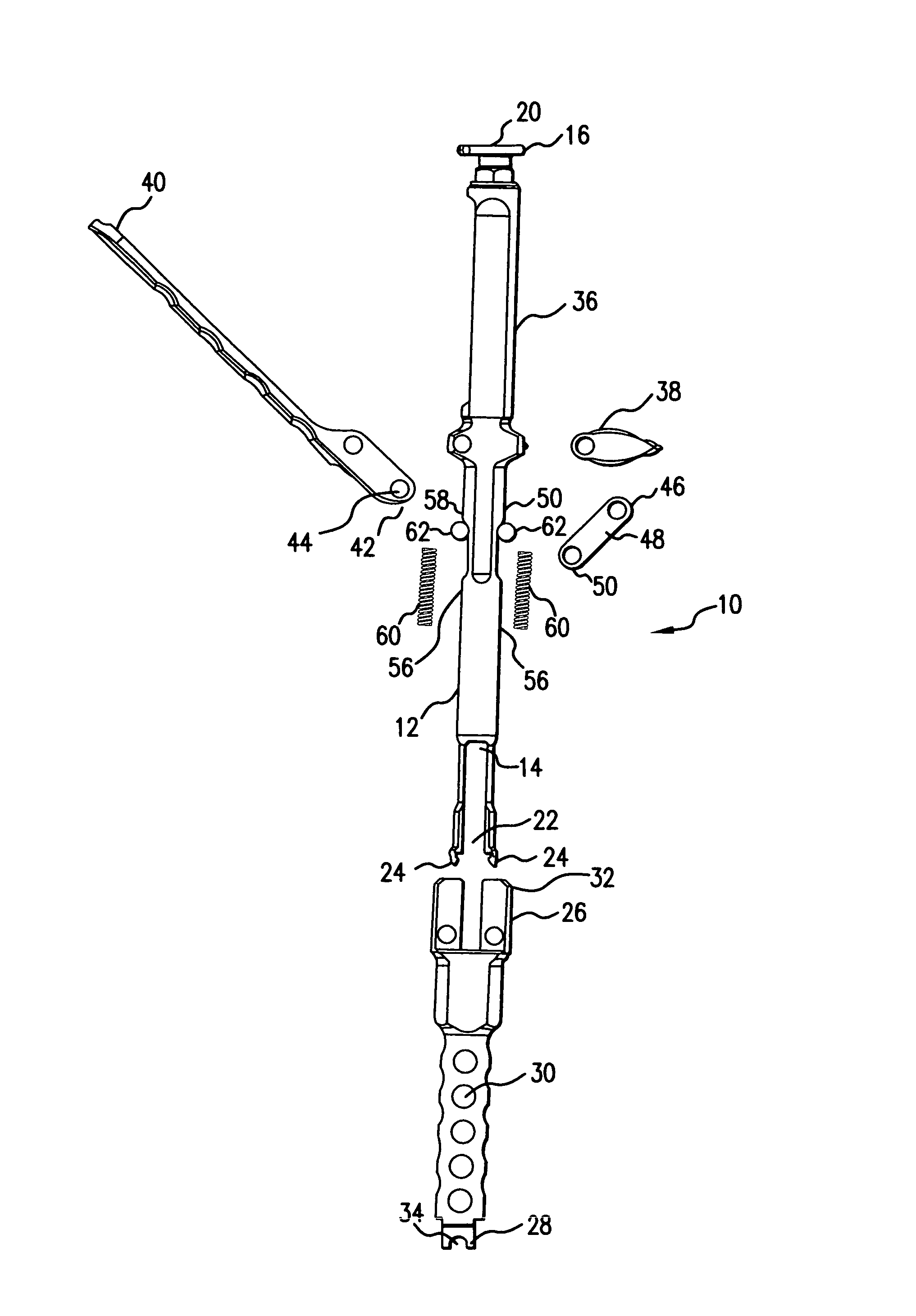
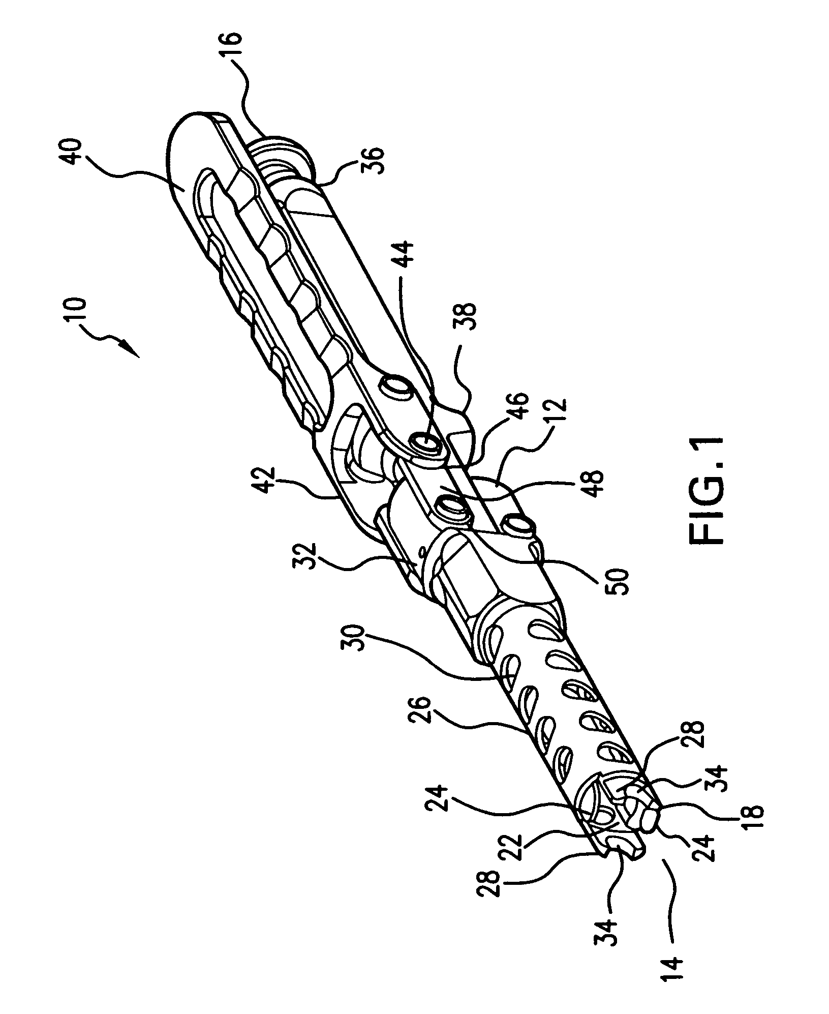
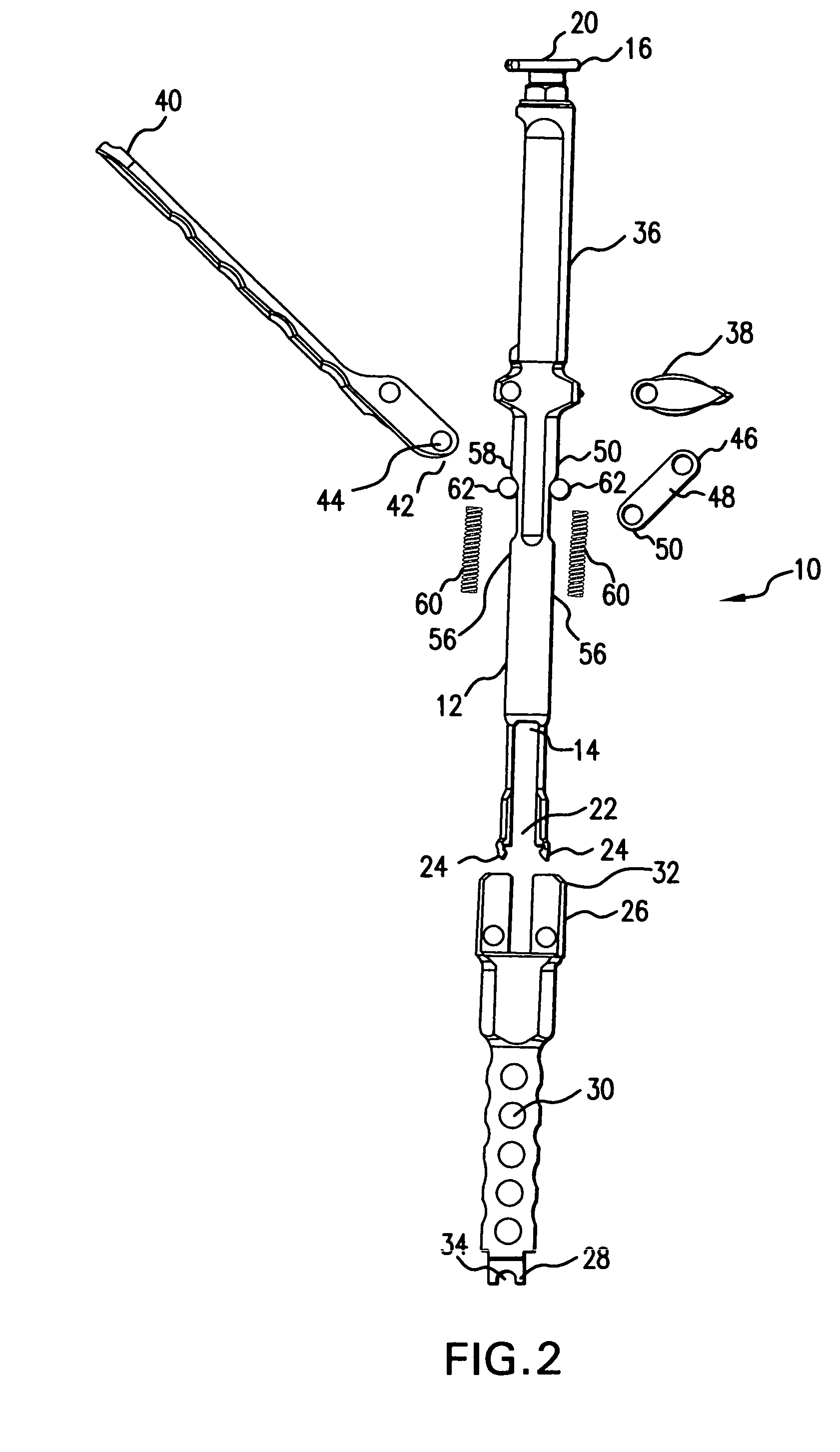
[0027]FIGS. 1-8 illustrate an example of a cannulated connecting rod reducing device, generally shown at 10, which, in one simple action such as squeezing a lever, can reduce a posteriorly introduced rod into a receiving slot in the head of a bone screw and then provide an anti-torque effect to the bone screw while a bone screw locking cap introduced through the cannula of the device is secured to the bone screw.

[0028]As shown in FIGS. 1-8 the cannulated rod reducing device 10 is an elongated surgical instrument having a device housing 12 that defines a...


PUM


Abstract

Provided is a novel rod reducing device for use in spinal fixation procedures. The device is capable with a single action of securely grasping the head of a bone screw while reducing a connecting rod into the head of the bone screw and while in position on the bone screw provide a cannula access for a bone screw locking cap and tightening instrument and securing the bone screw during the tightening of the locking cap so as to provide an anti-torque effect. The device is also capable of releasing from the bone screw with a reversal of the single action used to activate the device. A method of using the device and a kit wherein the device is one component is also provided.

Description

BACKGROUND[0001]1. Technical Field[0002]The present invention relates to orthopedic surgery, and in particular to devices for stabilizing and fixing the bones and joints of the body. Particularly, the present invention relates to an instrument capable of reducing a spinal rod into position in a rod receiving notch in the head of a bone screw and holding the same in position and providing anti-torque effect on the bone screw while a bone screw locking cap is attached to the head of the bone screw.[0003]2. Background Art[0004]The spinal column is a complex system of bones and connective tissues that provides support for the human body and protection for the spinal cord and nerves. The adult spine is comprised of 24 vertebral bodies, which are subdivided into three areas including seven cervical vertebrae, 12 thoracic vertebrae and five lumbar vertebrae. Between each vertebral body is an intervertebral disc that cushions and dampens the various translational and rotational forces exert...

Claims


Application Information

Patent Timeline
Patent Type & Authority Patents(United States)
IPC IPC(8): A61F5/00
CPCA61B17/7086A61B17/7032A61B17/7091
Inventor JONES, SCOTT A.ROCK, ANDY
Owner K2M
Why Eureka
Try Eureka