
Sensing method using self-capacitance and mutual-capacitance alternatively to reduce touch noises

Active Publication Date: 2014-07-24
FOCALTECH SYSTEMS LTD
View PDF5 Cites 47 Cited by
  • Summary
  • Abstract
  • Description
  • Claims
  • Application Information

AI Technical Summary

Benefits of technology

The patent describes a way to reduce touch noises in handheld devices by using self-capacitance and mutual-capacitance to improve accuracy. The technical effect is to make it easier to detect when someone touches a device, and to minimize the interference caused by those touches.

Problems solved by technology

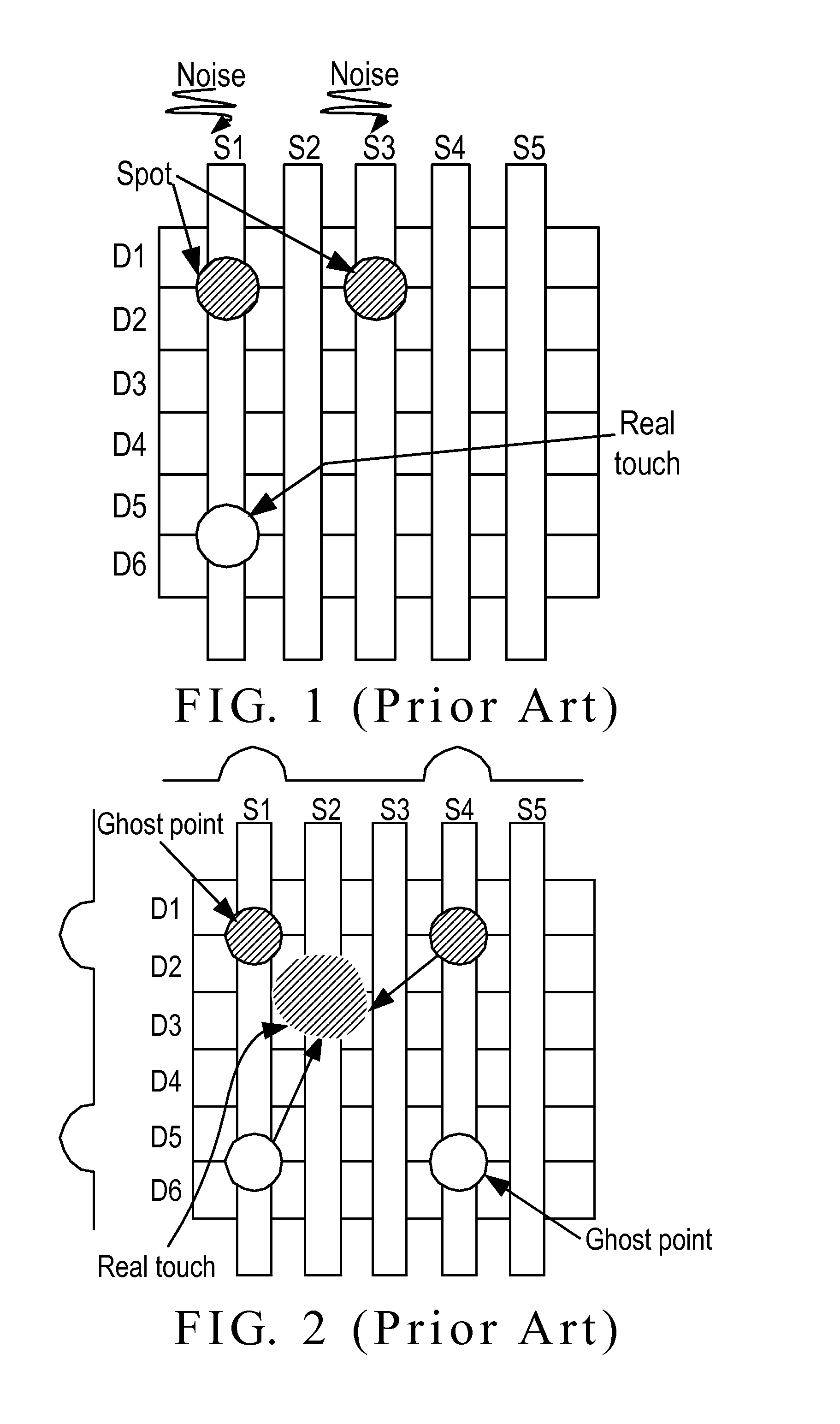
However, in the process of fetching touch data, due to noise interferences on the capacitive sensor circuit, touchpad unit, and even driver circuit, an external noise to ground interference, or internal noise interferences generated in the ICs, the touch data may be distorted and drifted, resulting in that noisy spots are presented, as shown in FIG. 1, or real touch point is disappeared or coordinate is shifted.
However, when there are external noises or the panel receives noises, it is found that the mutual-capacitance sensing is sensitive to the noise interference on the same sensing line.
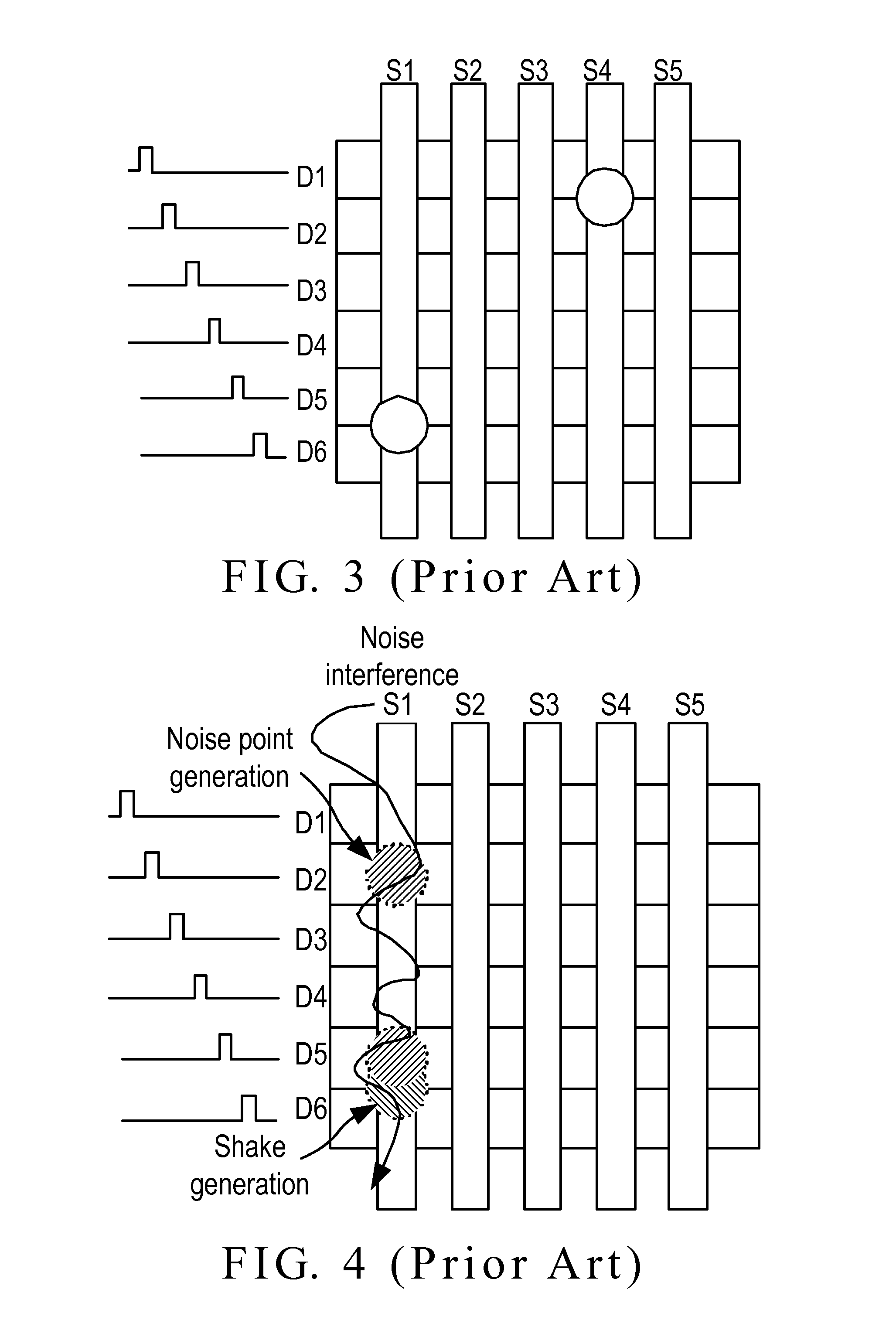
However, when the touch system uses an independent power, which is connected to ground that is different from the real earth ground, this may cause the coordinates of the touch points to greatly shake or generate other noisy spots, so that the steady touch system is negatively affected, as shown in FIG. 4.
Also, difficulties are presented on a slight capacitance change and smaller input voltage with respect to other circuits.
The cited conditions are disadvantageous to noise cancellation.
However, for a small signal which is sensitive to noises, a slight noise can cause an incorrect data determination, or even the original small signal is filtered out.
Thus, for the touch system, the use of filter circuit is not satisfactory.
However, such a way increases the power consumption and is not suitable for handheld devices.
In addition, the circuit before the integrator is affected by noises which are difficult to be canceled, even the voltage of the driving signal is enlarged.
However, it is not easy to implement the adjustable noise threshold because the touch IC cannot clearly know the noise source.
However, since the noise source is not clear, such a way cannot avoid all noise frequencies.
Furthermore, the three-frequency driving signal inevitably uses more system resources, resulting in reducing the report rate of the touch points and consuming more power.

Method used


Image

  • Sensing method using self-capacitance and mutual-capacitance alternatively to reduce touch noises
  • Sensing method using self-capacitance and mutual-capacitance alternatively to reduce touch noises
  • Sensing method using self-capacitance and mutual-capacitance alternatively to reduce touch noises

Examples


Embodiment Construction

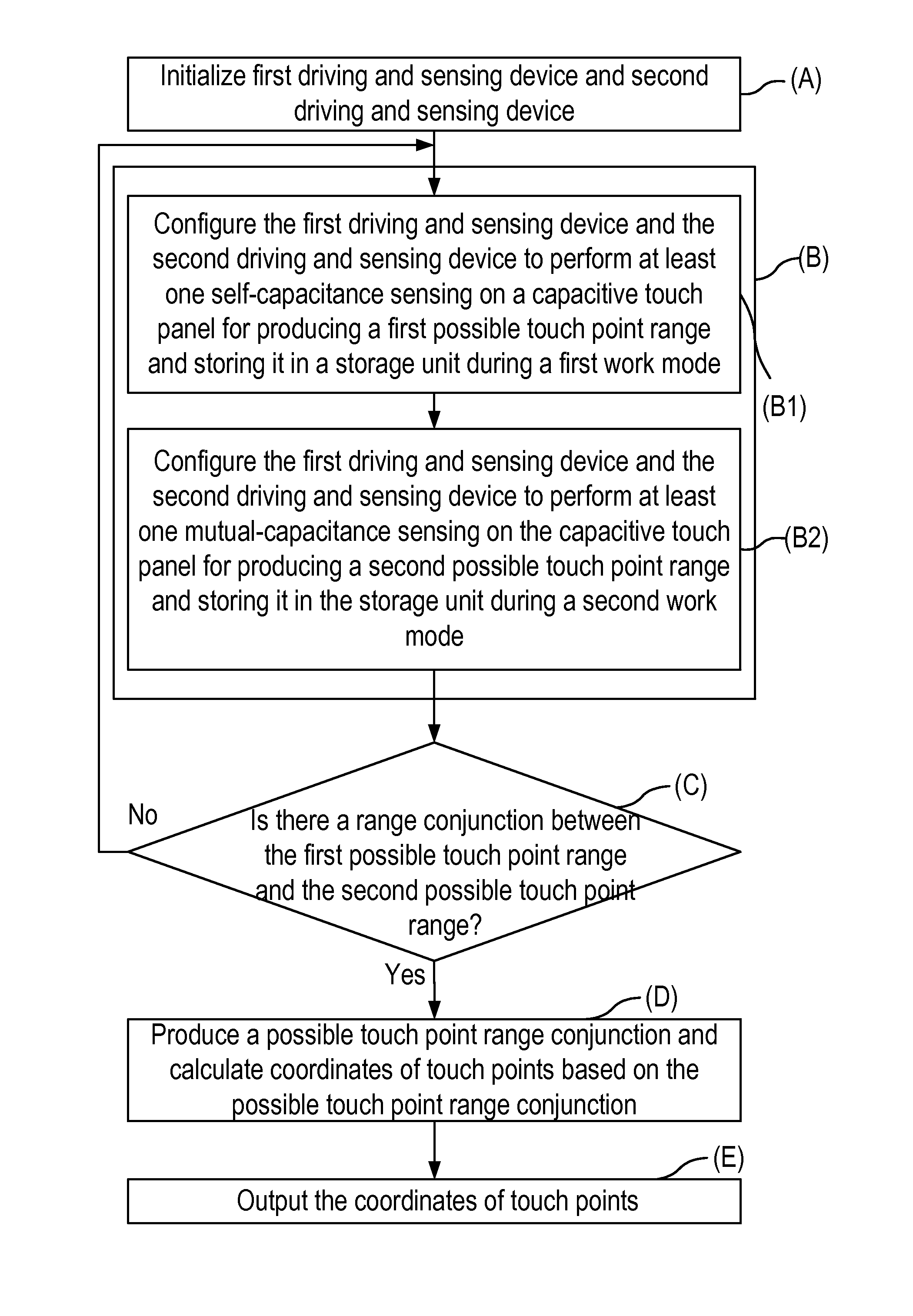
[0042]The invention provides a sensing method using self-capacitance and mutual-capacitance alternatively to reduce touch noises in a capacitive multi-touch system. FIG. 10 is a block diagram of the capacitive multi-touch system 100 according to the invention. FIG. 11 is a flowchart of the sensing method using self-capacitance and mutual-capacitance alternatively to reduce touch noises according to the invention. As shown in FIG. 10, the capacitive multi-touch system 100 includes a capacitive touch panel 110, a first driving and sensing device 120, a second driving and sensing device 130, and a control device 140.

[0043]The capacitive touch panel 110 has m first conductor lines 112 distributed in a first direction (X-axis direction) and n second conductor lines 111 distributed in a second direction (Y-axis direction), wherein m and n are each an integer greater than one, and the first direction is vertical to the second direction.

[0044]Each of the first driving and sensing device 120...


PUM


Abstract

In a sensing method using self-capacitance and mutual-capacitance alternatively to reduce touch noises, a control device configures a first driving and sensing device and a second driving and sensing device to perform an initialization. The control device configures the first and second driving and sensing devices to perform at least one self-capacitance sensing for producing a first possible touch point range during a first work mode. Then, the control device configures the first and second driving and sensing devices to perform at least one mutual-capacitance sensing for producing a second possible touch point range during a second work mode. The control device determines if there is range conjunction between the first and second possible touch point ranges. The control device produces a possible touch point range conjunction and calculates coordinates of touch points based on the possible touch point range conjunction.

Description

BACKGROUND OF THE INVENTION[0001]1. Field of the Invention[0002]The present invention relates to the technical field of touch panels and, more particularly, to a sensing method using self-capacitance and mutual-capacitance alternatively to reduce touch noises.[0003]2. Description of Related Art[0004]The principle of touch panels is based on different sensing manners to detect a voltage, current, acoustic wave, or infrared to thereby detect the coordinate of a touch point on a screen as touched by a finger or other medium. For example, a resistive touch panel uses a potential difference between the upper and lower electrodes to compute the position of a pressed point for detecting the location of the touch point, and a capacitive touch panel uses a capacitance change generated in an electrostatic combination of the arranged transparent electrodes with the touching part of a human body to generate a current or voltage for detecting the coordinate of the touching part.[0005]A typical c...

Claims


Application Information

Patent Timeline
IPC IPC(8): G06F3/044
CPCG06F3/044G06F3/04182G06F3/0446
Inventor HUANG, HSIN-MAOYU, HSIANG CHENGKUNG, CHIH-HUNGHUANG, SHIH-HSIN
Owner FOCALTECH SYSTEMS LTD
Learn More