System and Method for Selective Communication with RFID Transponders

a selective communication and transponder technology, applied in the field of rfid communication systems, can solve the problems of reducing the system complexity and cost of anti-collision management, and affecting the safety of users

Inactive Publication Date: 2005-05-05
ZIH CORP
View PDF12 Cites 38 Cited by
  • Summary
  • Abstract
  • Description
  • Claims
  • Application Information

AI Technical Summary

Benefits of technology

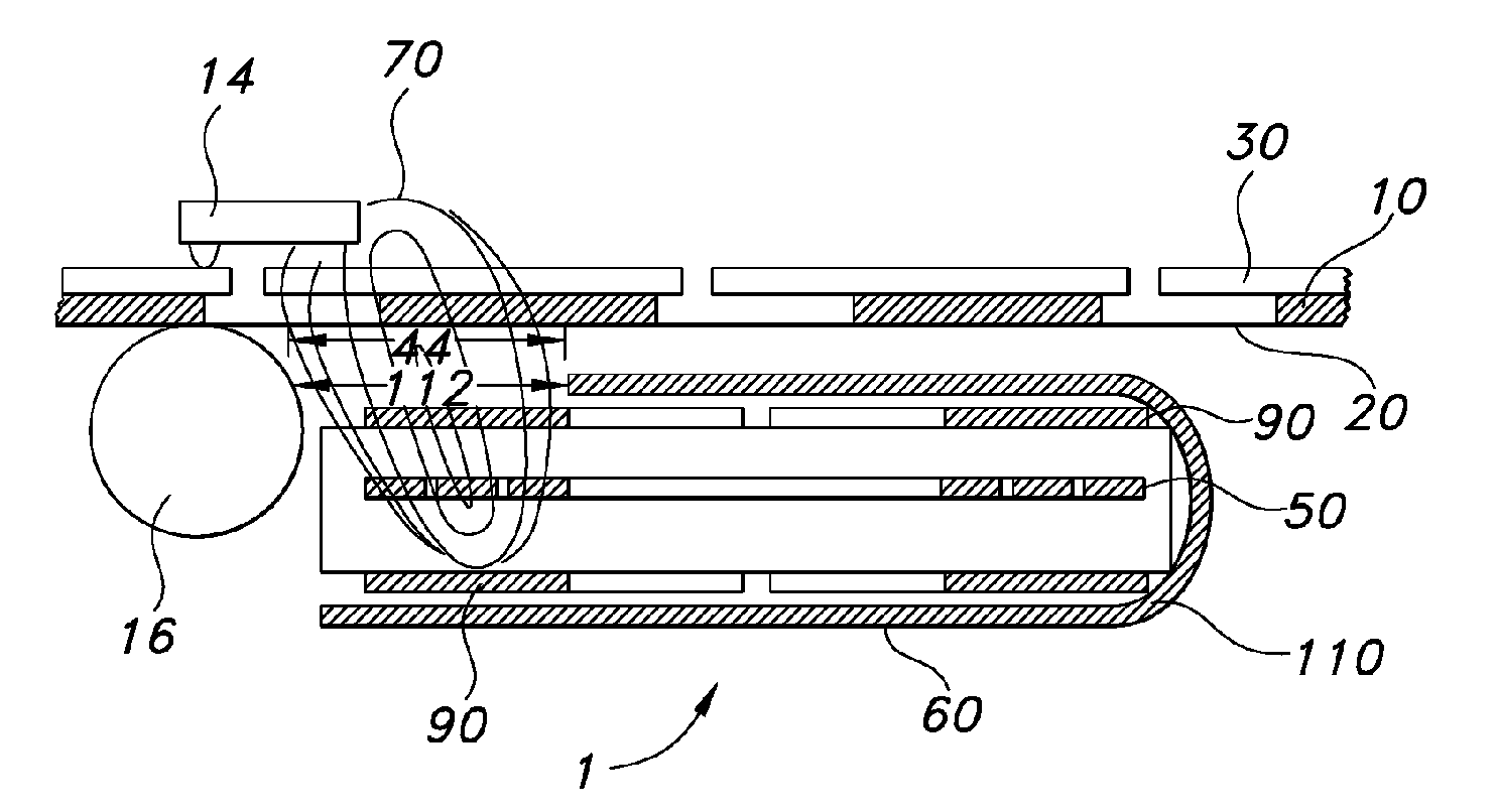
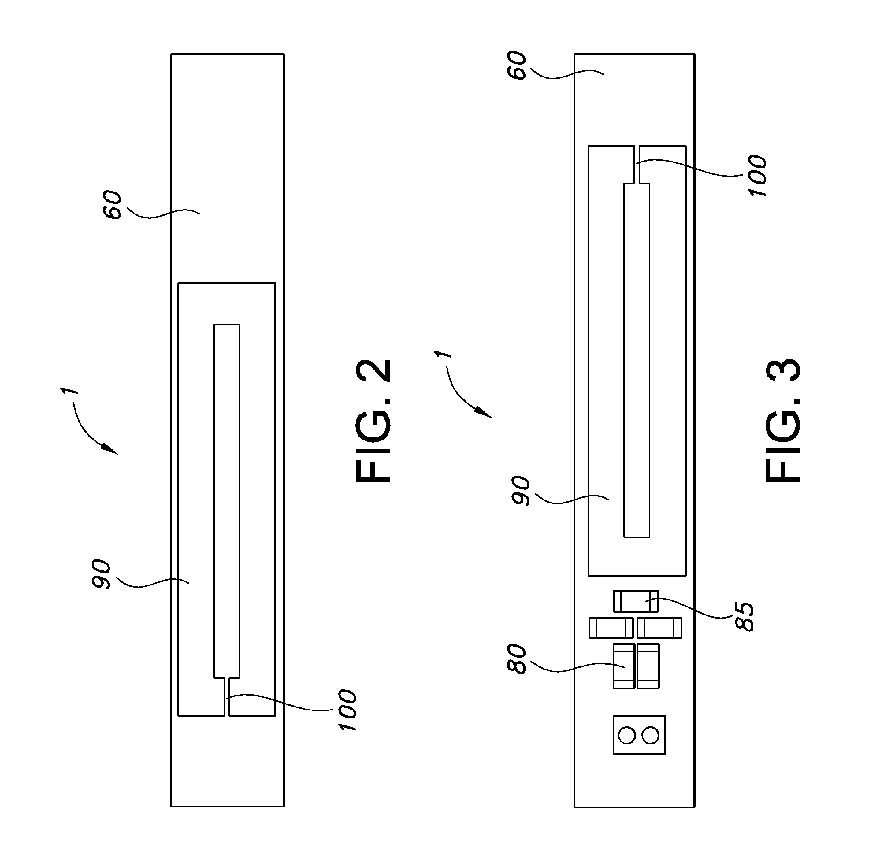
[0036] The magnetic coupling device 1 comprises a magnetic flux generator and a magnetic field pattern former, as will be described. The magnetic flux generator may comprise one or more coils responsive to RF signals supplied by the transceiver 42. The coils may take the form of a planar elongated coil created, for example, by conductor(s) coupled with a coil support structure. The conductors and coil support structure may comprise, for example, a coil trace(s) 50 on and or within a multi-layered printed circuit board (PCB) 60. Coil trace(s) 50 may be formed without sharp corners to minimize creation of impedance discontinuities.
[0039] The E-field suppressor shield 90 may be created, for example, by forming another conductive layer on one or both sides of the PCB 60 containing coil trace 50, as shown in FIGS. 2, 3, 4 and 6A and 6B. The E-field suppressor shield 90 may be formed as a gapped loop that covers the magnetic coupling device radiating coil trace(s) 50 completely with the exception of a small open circuit 100, as shown in FIGS. 1 and 2. The purpose of the open circuit 100 is to prevent Eddy current flow in the E-field suppressor shield 90 which would cause signal losses.
[0049] The compact size of the magnetic coupling device 1 and the lack of any other shielding requirements allows the economical addition of sequentially spaced multiple RFID transponder format read and or write capability to a range of sequential RFID transponder transport devices, for example label printers, to form a selective transponder communication module.
[0057] The transponder is 16 mm wide and 47 mm long. In a landscape orientation with respect to the direction of media travel, as soon as the leading edge of the transponder coil clears either side of a roughly 17 mm target area, it is unable to be activated. The other curves demonstrate responses of a range of different RFIDs using the same test configuration. Allowing for the possible use of all the different transponders with the same magnetic coupling device configuration provides a usable target area of 25 mm or less. With this degree of selectivity provided by the present invention, transceiver power levels can be raised to provide a comfortable safety margin without concern for energizing adjacent transponders even when the transponders are closely spaced. Conversely, the target area is wide enough that pinpoint positioning of the transducer is not necessary for reliable communication.
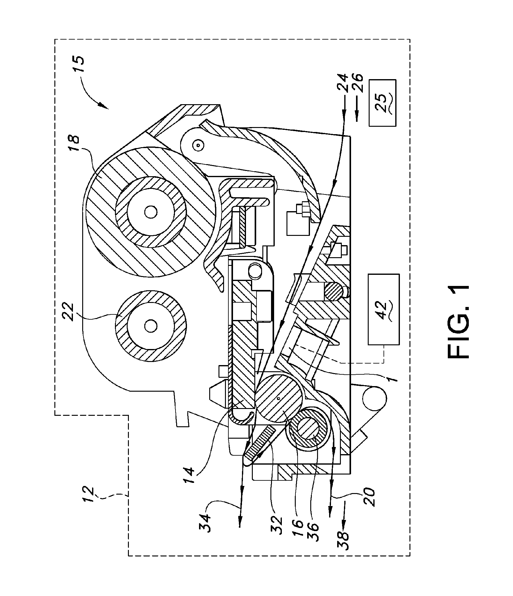
[0061] The magnetic field pattern former 110 may be easily adjusted for different desired magnetic field directions and or shapes during manufacture by varying the size, configuration and or location of the magnetic field pattern former 110 applied to the PCB 60 or other coil support structure. Table of Parts 1magnetic coupling device10transponder12printer14printhead15printhead sub-assembly16platen roller18supply roll20carrier substrate22take up reel24web25media conveyance26feed path30facestock32tear bar34label exit path36roller38carrier exit path42transceiver44target area50coil trace60printed circuit board70field pattern80capacitors85resistor90E-field suppressor shield100 open circuit110 field pattern former112 gap

Problems solved by technology

When multiple RFID transponders are within the range of the same RF magnetic field they will each be energized and attempt to communicate with the transceiver, potentially causing errors in reading and or writing to a specific RFID transponder.
However, anti-collision management increases system complexity and cost.
Further, anti-collision management is blind.
It cannot recognize where a responding transponder is located in the RF magnetic field.
This requires that the individual transponders have cumbersome shielding or a significant physical separation.
The extra carrier substrate increases materials costs and the required volume of the RFID media bulk supply for a given number of RFID transponders.
Having increased spacing between RFID transponders may also slow overall throughput.
When the size or form factor of the utilized RFID transponder is changed, the RF shielding and or anechoic chamber configuration may also require reconfiguration, adding cost and complexity and reducing overall productivity.
This may be very difficult to accomplish if the transponder must be interrogated in a shielded housing or chamber.

Method used


Image

  • System and Method for Selective Communication with RFID Transponders
  • System and Method for Selective Communication with RFID Transponders
  • System and Method for Selective Communication with RFID Transponders

Examples


Embodiment Construction

[0026] The present invention concerns apparatus and method which enables an RFID transceiver (sometimes termed herein an “interrogator”) to communicate selectively and exclusively with a single RFID transponder when one or more other transponders are in close proximity, without the need for physical isolation or cumbersome shielded housings or chambers.

[0027] The invention is useful in the loading or reading of transponders, for example on an assembly line, in distribution centers or warehouses where on-demand RFID labeling is required, and in a variety of other applications. In many applications a transponder or a number of transponders are mounted on a label, ticket, tag, card or other media carried on a liner or carrier. It is often desirable to be able to print on the media before, after, or during communication with a transponder. Although this invention is disclosed here in a specific embodiment for use with a direct thermal or thermal transfer printer, it may also be used wi...


PUM


Abstract

A system having an RFID transceiver is adapted to communicate exclusively with a single RFID transponder located in a predetermined confined transponder target area. The system includes a magnetic coupling device comprising a magnetic flux generator responsive to a radio frequency input signal and a magnetic field pattern former. The pattern former is configured to collect flux produced by the flux generator and to form a field pattern in the location of the transponder target area. The system establishes, at predetermined transceiver power levels, a mutual magnetic coupling which is selective exclusively for a single transponder located in the transponder target area.

Description

BACKGROUND OF INVENTION [0001] 1. Field of the Invention [0002] The invention relates to RFID communication systems which are selective for an individual transponder located in a predetermined target area, to the exclusion of other transponders, and to printers and other larger systems having such RFID communication systems. [0003] 2. Description of Related Art [0004] Inductively coupled radio frequency identification (RFID) technology allows data acquisition and or transmission from and or to active (battery powered) or passive RFID transponders using RF magnetic induction. To read or write from and or to an RFID transponder, the RFID transponder is exposed to an RF magnetic field that couples with and energizes the RFID transponder through magnetic induction and transfers commands and data using a predefined “air interface” RF signaling protocol. [0005] When multiple RFID transponders are within the range of the same RF magnetic field they will each be energized and attempt to com...

Claims


Application Information

Patent Timeline
Patent Type & Authority Applications(United States)
IPC IPC(8): G06K7/00G06K7/08
CPCG06K7/0008G06K17/0025G06K7/087
Inventor TSIRLINE, BORIS Y.HOHBERGER, CLIVE P.GAWELCZYK, ROBERT
Owner ZIH CORP
Why Eureka
Try Eureka