Gate valve
- Summary
- Abstract
- Description
- Claims
- Application Information
AI Technical Summary
Benefits of technology
Problems solved by technology
Method used
Image

Examples
embodiment 1
[0028] Gate valves according to preferred embodiments of the present invention will now be described with reference to the drawings.
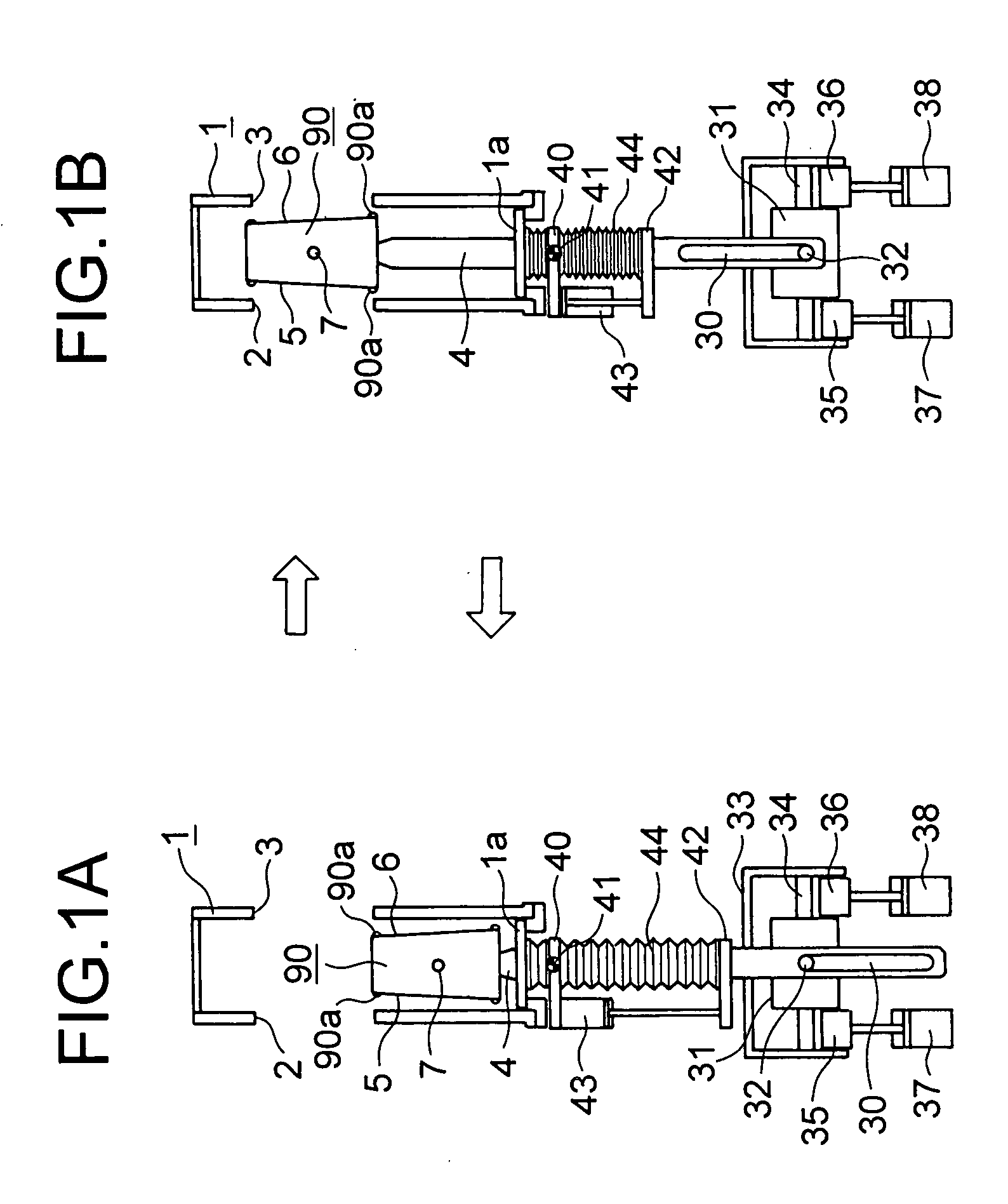
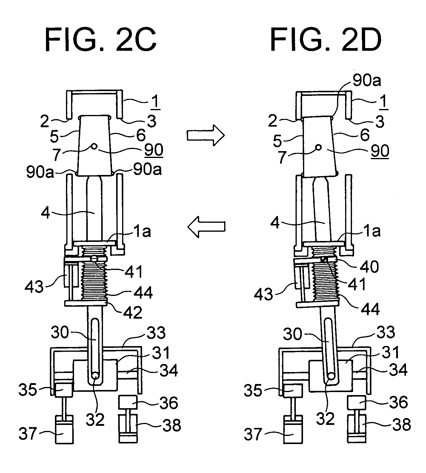
[0029]FIGS. 1A and 1B and FIGS. 2C and 2D show a gate valve according to Embodiment 1 of the present invention, reversibly illustrating the opening and closing operations thereof.
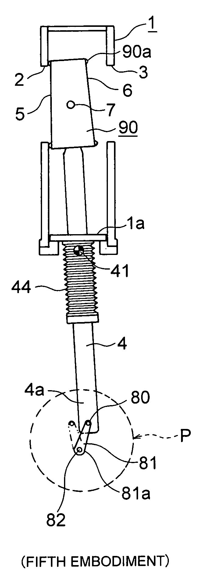
[0030] In FIGS. 1A and 1B, reference numeral 1 indicates a valve box generally formed in a box-like configuration and having first and second openings 2 and 3. In the valve box 1, a valve rod 4 is provided so as to be capable of ascending and descending, and, at the upper end of the valve rod 4, there is provided a valve plate 90 having first and second tapered valve plate surfaces 5 and 6 on its sides, with the valve plate 90 being rotatable through a rotatably-supporting portion 7. The valve plate surfaces 5 and 6 are tapered upwards from below.
[0031] As shown in FIGS. 11 and 12, the valve plate 90, having the valve plate surfaces 5 and 6, is provided so as to be rotatable...
embodiment 2
[0042] Next, FIGS. 4A, 4B, and 4C show the construction of a gate valve according to Embodiment 2 of the present invention. The components, which are the same as those of Embodiment 1, are indicated by the same reference numerals, and a description of such components will be omitted. Although not shown in the figure, this embodiment is equipped with the rotatably-supporting member 40, the fixing portions 40a, and the rotatably-supporting portions 41, which are of the same construction as those in FIGS. 1A and 1B. The raising and lowering of the valve rod 4 are not effected by the raising / lowering cylinder 43 of FIGS. 1A and 1B. Instead, an actuator 52 and the valve rod 4 are raised and lowered simultaneously by using a cylinder or the like (not shown).
[0043] The lower portion 4a of the valve rod 4 extends through a fixation member 50 so as to be capable of operating, and a rod 53 of the actuator 52 is connected to this lower portion 4a through the intermediation of a rotatably-supp...
embodiment 3
[0049]FIGS. 5A through 7 are schematic diagrams showing a gate valve according to Embodiment 3. The components, which are the same as, or equivalent to those of FIGS. 1A through 1C are indicated by the same reference numerals, and a description of such components will be omitted. In the following, only the components differing from those of FIGS. 1A through 1C will be described.
[0050] Provided on the lower portion 4a of the valve rod 4 is a bar-like protrusion 60, which is passed through and engaged with first and second cam holes 63 and 64 of plate-like first and second cam members 61 and 62 laterally stacked together.
[0051] The cam members 61 and 62 each are connected to first and second piston rods 67a and 68a of first and second cam raising / lowering cylinder 67 and 68 through the intermediation of first and second arms 65 and 66.
[0052] The first and second cam members 61 and 62 are raised and lowered through selective driving of the first and second cam raising / lowering cylin...
PUM
 Abstract
Description
Claims
Application Information
 - Generate Ideas
- Intellectual Property
- Life Sciences
- Materials
- Tech Scout
- Unparalleled Data Quality
- Higher Quality Content
- 60% Fewer Hallucinations
Browse by: Latest US Patents, China's latest patents, Technical Efficacy Thesaurus, Application Domain, Technology Topic, Popular Technical Reports.
© 2025 PatSnap. All rights reserved.Legal|Privacy policy|Modern Slavery Act Transparency Statement|Sitemap|About US| Contact US: help@patsnap.com