Optical element, method of molding optical element, and mold
a technology of optical elements and molds, applied in the field of optical elements, can solve the problems of not necessarily uniformly left in the movable mold member of the conventional optical element, and achieve the effect of high accuracy and higher accuracy
- Summary
- Abstract
- Description
- Claims
- Application Information
AI Technical Summary
Benefits of technology
Problems solved by technology
Method used
Image
Examples
first embodiment
[0049] First, an optical element according to the first embodiment of the present invention will be described with reference to the accompanying drawings.
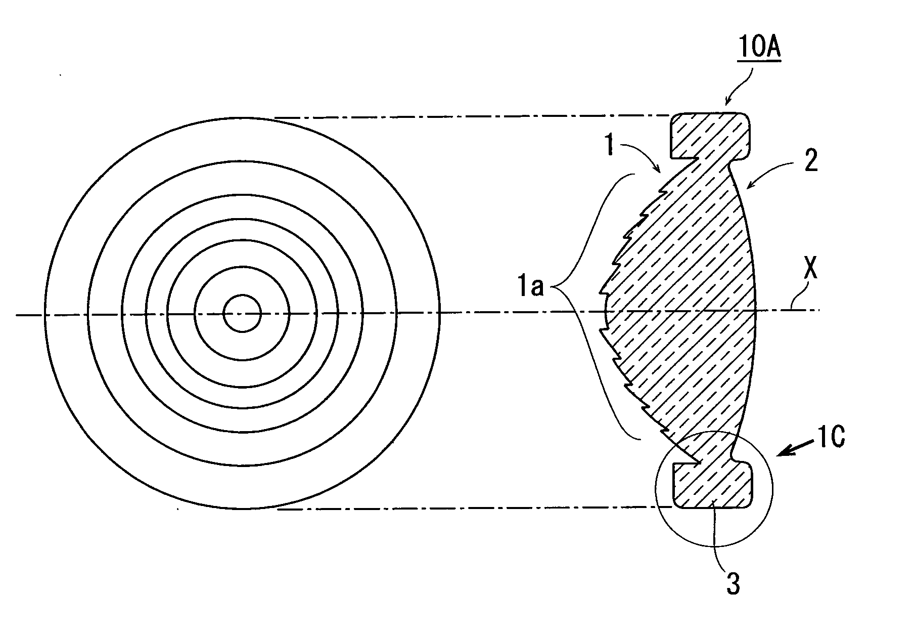
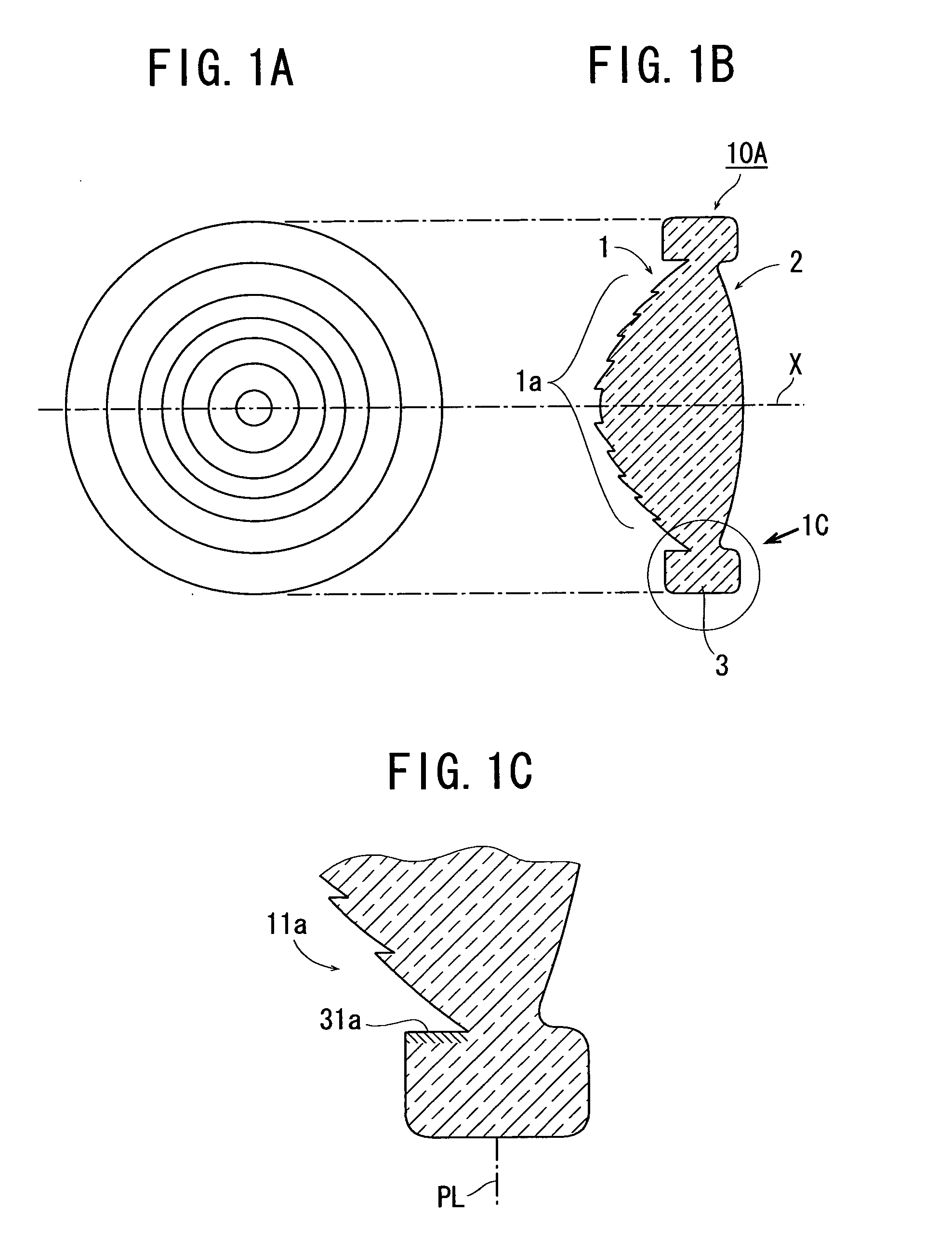
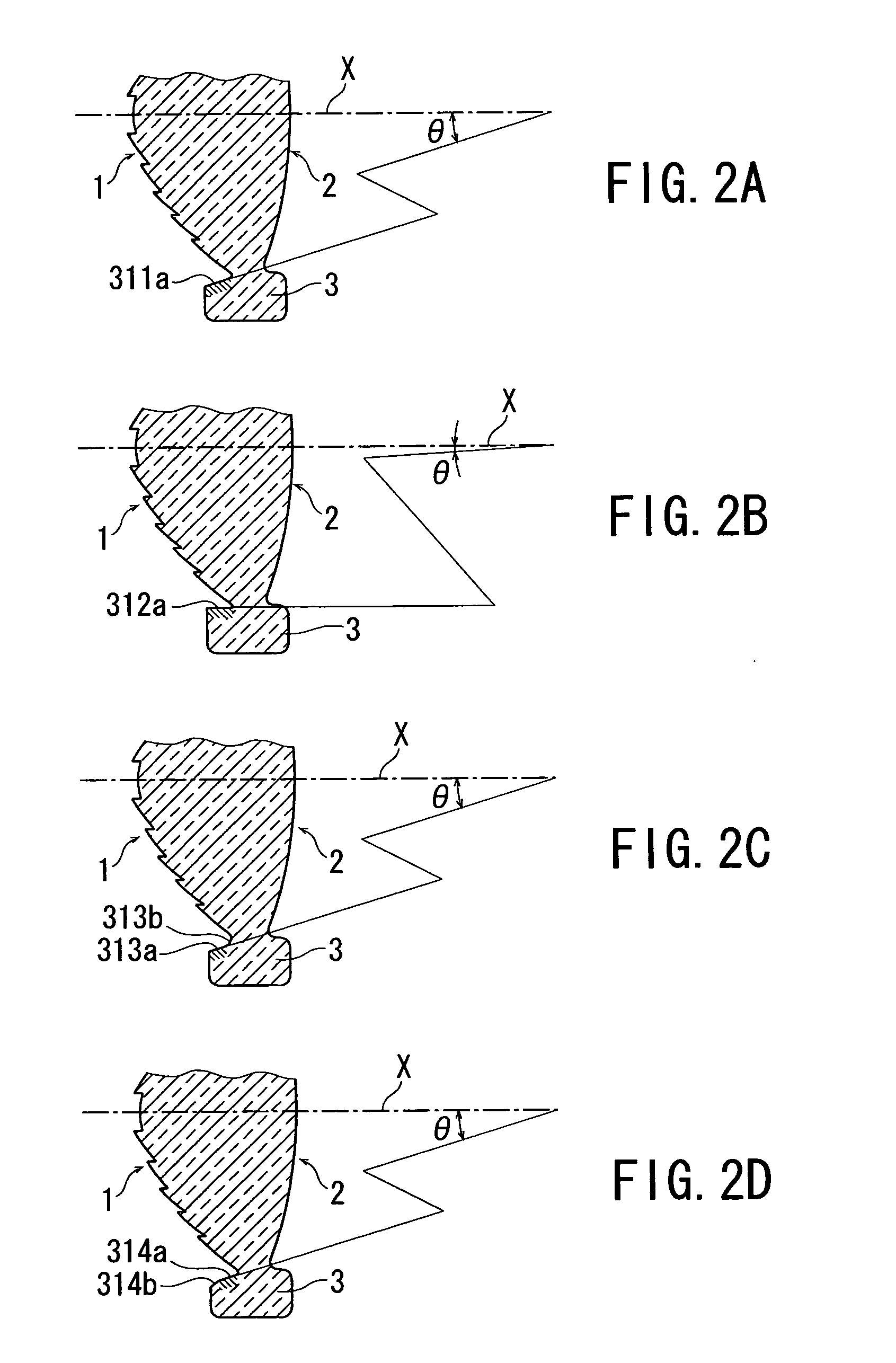
[0050]FIGS. 1A to 1C are a front view, optical-axis sectional view, and enlarged optical-axis sectional view of the flange section, respectively, of an optical element according to the first embodiment of the present invention. FIGS. 2A to 2D are optical-axis sectional views showing an example of the heat shrinkage-inhibiting portion of the flange section shown in FIG. 1C.
[0051] Referring to FIGS. 1A to 1C and 2A to 2D, an optical element 10A is a single lens having a positive power, and includes an object-side surface 1 formed with an optical functional section 1a having a fine structure 11a, an image-side surface 2 having an aspherical optical functional section, and a flange section 3 formed around the periphery of the optical functional section. In FIG. 1C, reference symbol PL denotes the parting line of molding.
[0052] The o...
second embodiment
[0062] An optical element according to the second embodiment will be described with reference to the accompanying drawings. FIGS. 5A to 5C are a front view, optical-axis sectional view, and enlarged optical-axis sectional view of the flange section, respectively, of the optical element according to the second embodiment of the present invention.
[0063] Referring to FIGS. 5A to 5C, an optical element 10B is a single lens having a positive power, and includes an object-side surface 1 having an optical functional section with a fine structure, an image-side surface 2 having an aspherical optical functional section, and a flange section 3 formed on the periphery. The optical element 10B is a molded product. The object-side surface 1 of the optical element 10B is formed with the movable mold member of a mold, and its image-side surface 2 is formed with the fixed mold member of the mold. In FIG. 5C, reference symbol PL denotes the parting line of molding.
[0064] A force (separation force)...
third embodiment
[0069] An optical element according to the third embodiment will be described with reference to the accompanying drawings. FIGS. 6A to 6C are a front view, optical-axis sectional view, and enlarged optical-axis sectional view of the flange section, respectively, of the optical element according to the third embodiment. In the optical element of the third embodiment, the functions of the first and second embodiments are combined to obtain a synergetic effect. A description will be made mainly on portions that are different from their counterparts of the first and second embodiments.
[0070] Referring to FIGS. 6A to 6C, an optical element 10C is a single lens having a positive power, and includes an object-side surface 1 having an optical functional section with a fine structure, an image-side surface 2 having an aspherical optical functional section, and a flange section 3 formed on the periphery. The optical element 10C is a molded product. The object-side surface 1 of the optical el...
PUM
| Property | Measurement | Unit |
|---|---|---|
| angle | aaaaa | aaaaa |
| angle | aaaaa | aaaaa |
| angle | aaaaa | aaaaa |
Abstract
Description
Claims
Application Information
 - R&D
- Intellectual Property
- Life Sciences
- Materials
- Tech Scout
- Unparalleled Data Quality
- Higher Quality Content
- 60% Fewer Hallucinations
Browse by: Latest US Patents, China's latest patents, Technical Efficacy Thesaurus, Application Domain, Technology Topic, Popular Technical Reports.
© 2025 PatSnap. All rights reserved.Legal|Privacy policy|Modern Slavery Act Transparency Statement|Sitemap|About US| Contact US: help@patsnap.com


