

Over-current protection device and manufacturing method thereof
a technology of over-current protection and manufacturing method, which is applied in the direction of resistors, resistor details, electrical devices, etc., can solve the problems of lifetime and reliability degradation of over-current protection devices, and achieve the effect of fast dissipation of heat generation
- Summary
- Abstract
- Description
- Claims
- Application Information
AI Technical Summary
Benefits of technology
Problems solved by technology
Method used
Image

Examples
first embodiment
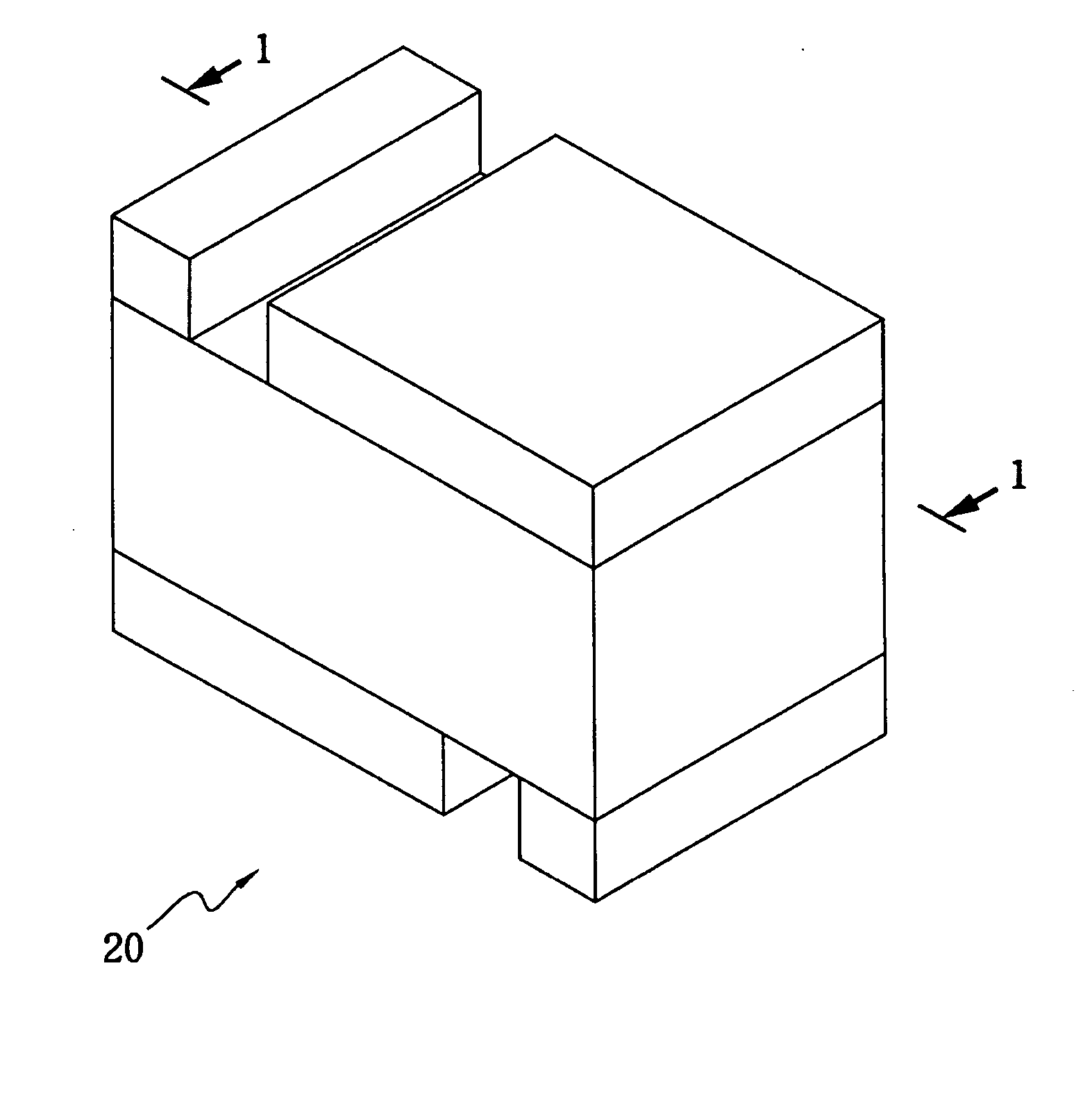
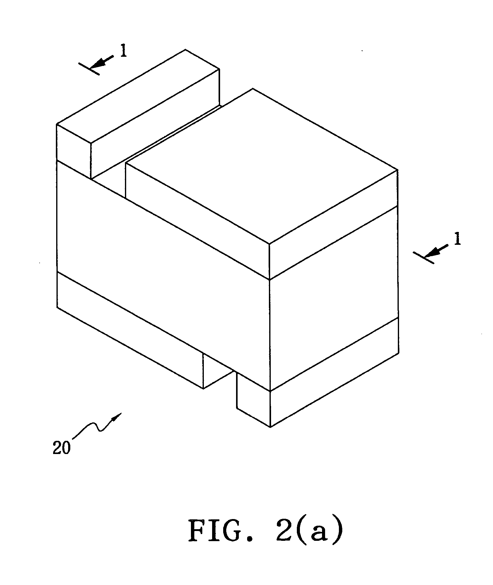
[0020] Referring to FIGS. 2(a)-2(b), FIG. 2(a) illustrates a perspective diagram of an over-current protection device in accordance with the present invention, and FIG. 2(b) illustrates a cross-section diagram along the line 1-1 in FIG. 2(a). An over-current protection device comprises a PTC material layer 201, two electrode layers 202, an adhesive layer 203, a heat dissipation layer 204, two isolation layers 207 and 208, two conductive bars 209 and two soldering electrode layers 205 and 206. The PTC material layer 201 is sandwiched between the two electrode layers 202 to form a PTC component 21. The PTC material layer 201 is made from a polymeric positive temperature coefficient (PPTC) material. The adhesive layer 203, acting as a thermal conductive medium and a connecter, is interposed between the PTC component 21 and heat dissipation layer 204. The adhesive layer 203 is made from an electrical conductive material or an electrical non-conductive material such as conductive silver ...
second embodiment
[0024]FIG. 3 illustrates an over-current protection device in accordance with the present invention. An over-current protection device 30 comprises a PTC material 301, two electrode layers 302, a adhesive layer 303, a heat dissipation layer 304, two isolation layers 307 and 308, two conductive bars 309 and two soldering electrode layers 305 and 306. A PTC component 31 is formed by that the PTC material 301 is stacked between the two electrode layers 302. In comparison with the over-current protection device 20, the conductive bars 309 of the over-current protection device 30 in the current embodiment extend from the upper soldering electrode layer 305 to the lower soldering electrode layer 306. Consequently, even though the adhesive layer 303 is made by a non-conductive material, the PTC component 31 can still be connected to the soldering electrode layer 305. Furthermore, regarding the manufacturing process, after the adhesive layer 303 and heat dissipation layer 304 are stacked on...
fifth embodiment
[0028] FIGS. 6(a)-6(g) illustrate a manufacturing method of the over-current protection device in accordance with the present invention. Referring to FIG. 6(a), two PTC components 61 are first provided, and each of the PTC components 61 is a PTC material 601 stacked between the two electrode layers 602. Afterward, openings 62 are formed on the PTC material 601 by etching and so on, as shown in FIG. 6(b). For simplifying the diagrams, FIG. 6(a)-6(b) only show one of the two PTC components 61. Referring to FIG. 6(c), the two PTC components 61 are stacked on each other by an adhesive layer 603, and the openings 62 are filled with a nonconductive material such as a solder-mask material to form isolation layers 607 and 608. Referring to 6(d), two adhesive layers 603 are employed so as to combine two heat dissipation layers 604 with the exposed electrode layers 602. As shown in FIG. 6(e), two through holes 602 are formed, after the two PTC components 61, two heat dissipation layers 604 an...
PUM
 Abstract
Description
Claims
Application Information