Circuit assembly, producing method of the same, distribution unit and bus bar substrate

a technology of circuit components and production methods, applied in the field of circuits, can solve the problems of difficult height reduction and height limitation, and achieve the effects of reducing the height reducing the size of the circuit component, and facilitating the operation of the assembly process

Inactive Publication Date: 2005-05-05
SUMITOMO WIRING SYST LTD
View PDF9 Cites 29 Cited by
  • Summary
  • Abstract
  • Description
  • Claims
  • Application Information

AI Technical Summary

Benefits of technology

[0034] According to the above structure, the mounting work can be effectively performed, even if the bus bars on the lower layers are stacked through the plural insulation layers. For example, although it is possible to use a semiconductor-switching device such as an FET in the case of using a switching device for turning an on-off mode of a circuit as the circuit component to be mounted in the mounting step, it is preferable to use a relay having heat radiation better than the semiconductor-switching device.
[0035] According to the circuit assembly constructed above, a size in height of the circuit component can be reduced in conjunction with maintaining a small occupation volume, especially an occupation are

Problems solved by technology

However, there has been a limitation in reduction of a size in height because the respective tab terminals of the relay and bus bar are co

Method used


Image

  • Circuit assembly, producing method of the same, distribution unit and bus bar substrate
  • Circuit assembly, producing method of the same, distribution unit and bus bar substrate
  • Circuit assembly, producing method of the same, distribution unit and bus bar substrate

Examples


first embodiment

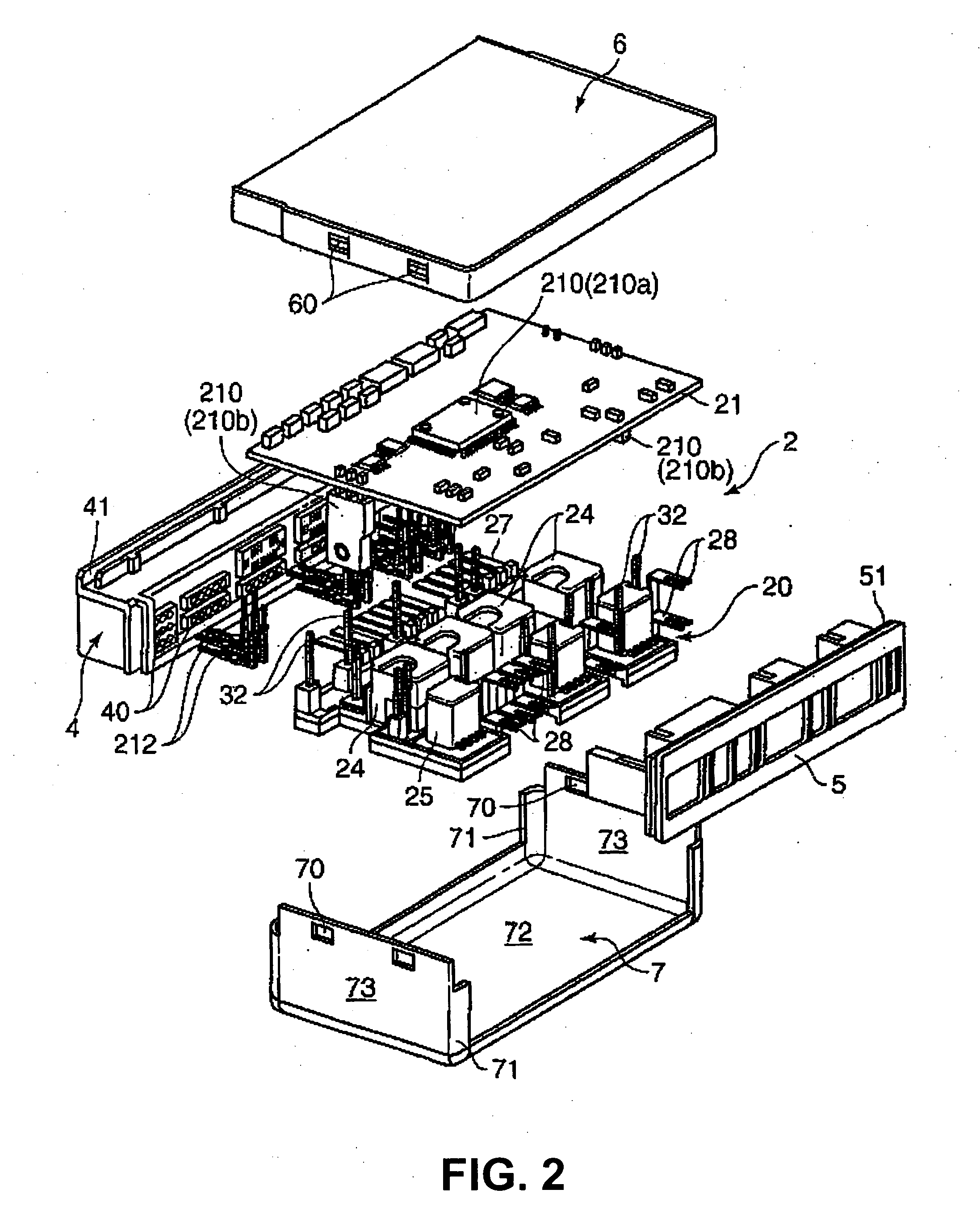
[0062] The circuit assembly 2 is formed into a flat block configuration having a substantially rectangular parallelepiped configuration. A number of connector terminals 27 having the given bus bars 22 bent in a hook-like shape are juxtaposed and projected forward from a square flat area A (see FIG. 6) at the front side of the circuit assembly 2. A plurality of fuse terminals 28 having the given bus bars 22 bent in a hook-like shape are substantially contained in the square flat area A and projected rearward in two stages at the rear side of the circuit assembly 2. A plurality of first relays 24 (four in the first embodiment) are mounted along a longitudinal direction (right and left direction) on the upper surface of the bus bar substrate 20 between the connector terminals 27 and the fuse terminals 28. One or more of the fuse terminals 28 are disposed closely to one another on the circuit assembly 2. Second relays 25 are mounted between the compacted fuse terminals 28 on the upper s...

second embodiment

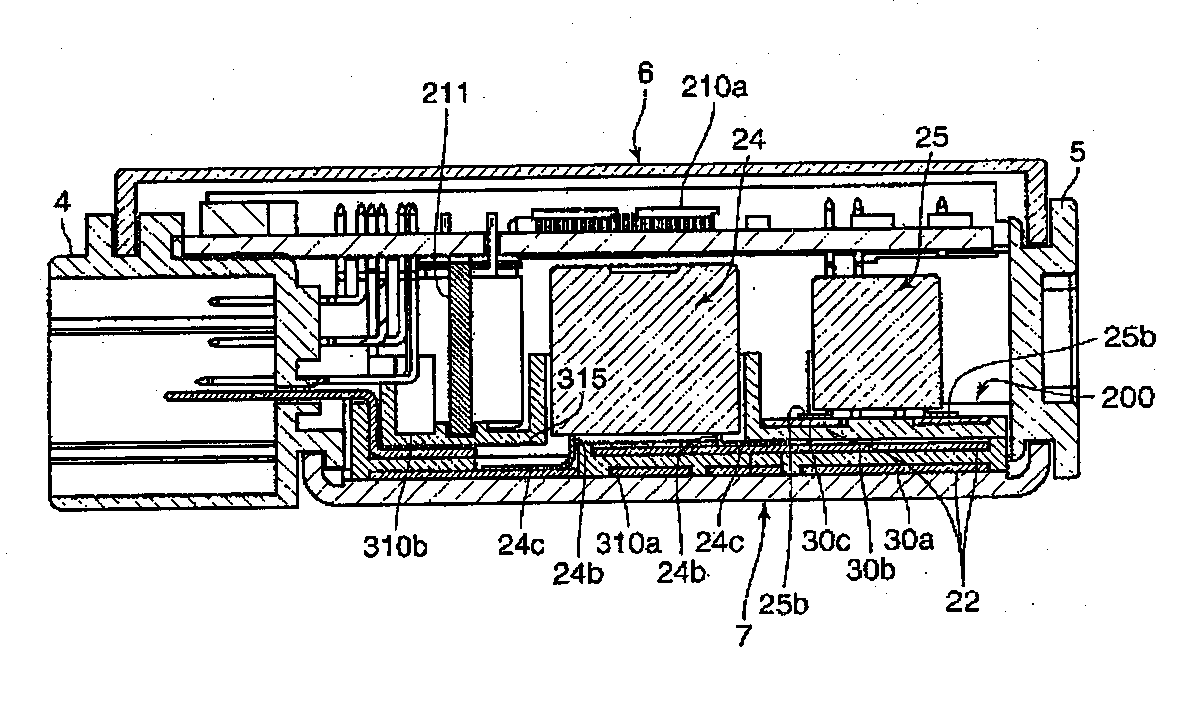
[0105]FIG. 14 is a cross sectional view of a distribution unit in accordance with the invention, illustrating the view similar to FIG. 4. FIG. 15 is a partial sectional view of the distribution unit corresponding to FIG. 6.

[0106] A circuit assembly of the second embodiment is significantly different from that of the first embodiment with respect to the fact that a first relay 24 is joined to the bus bars 22 on lower layers (first and second bus bar layers 30a and 30b) below the uppermost third bus bar layer 30c, a second insulation plate 310b is stacked on a contact piece 24c of a leg-like terminal 24b of the first relay 24 so that the second insulation plate 310b covers a connected portion between the bus bar 22 and the contact piece 24c, and the bus bars on a third bus bar layer 30c are disposed on the second insulation plate 310b. Consequently, a method for producing the circuit assembly 2 of the second embodiment is different from that of the first embodiment. Thus, an electrode...


PUM


Abstract

A circuit assembly includes a bus bar substrate and a first relay, in order to provide a circuit assembly in which a size in height can be reduced in conjunction with maintaining compactness, especially for a small occupation area in plan view by a simple structure. The bus bar substrate includes an electrical power circuit in which plural bus bar layers are stacked alternately through electrical insulation layers at plural levels. Each bus bar layer has plural bus bars arranged on the substantially same plane. The first relay is connected to the electrical power circuit through terminals. The first relay includes the terminals having contact pieces to be superposed on the bus bars along a layer surface of the bus bar. The contact piece of at least one of the terminals is joined by welding to a bus bar on a bus bar layer lower than the uppermost bus bar layer.

Description

CLAIM FOR PRIORITY [0001] The present invention claims priority to Japanese Patent Application JP 2003-376109 filed on Nov. 5, 2003. The entire disclosure of the prior application is hereby is incorporated by reference herein in its entirety. BACKGROUND OF THE INVENTION [0002] 1. Field of Invention [0003] This invention is directed to a circuit assembly and to a method of production in which a plurality of bus bars constituting an electrical power circuit are stacked through electrical insulation layers and to a circuit component for actuation in the electrical power circuit. [0004] 2. Description of Related Art [0005] Recently, a number of electronic units are installed on a vehicle such as a motor vehicle and a distribution unit is generally used for distributing an electrical power from a common electrical source on a vehicle to the respective electronic units. A circuit assembly to be installed in the distribution unit has been known. Such circuit assembly, as disclosed in, for ...

Claims


Application Information

Patent Timeline
IPC IPC(8): H05K7/06B60R16/02B60R16/023H02G3/16H05K1/00H05K1/02H05K1/14H05K1/18H05K3/20H05K3/32H05K3/46
CPCB60R16/0238H05K1/0298H05K2203/1115H05K3/202H05K3/328H05K1/144
Inventor ONIZUKA, TAKAHIROKITA, YUKINORI
Owner SUMITOMO WIRING SYST LTD
Why Eureka
Try Eureka