Demodulation apparatus and method for reducing time delay of on-channel repeater in terrestrial digital TV broadcasting system

a technology of terrestrial digital tv and time delay, which is applied in the field of digital television broadcasting service technology, can solve the problems of inefficiency in the aspect of frequency usage, interference may be generated between the same channels, and time-delayed multi-path signals cannot be removed in the equalization unit of the receiver, so as to reduce the time delay of an on-channel repeater and maximize the signal-to-noise ratio. , the effect of reducing the time delay

Inactive Publication Date: 2005-05-05
ELECTRONICS & TELECOMM RES INST
View PDF7 Cites 20 Cited by
  • Summary
  • Abstract
  • Description
  • Claims
  • Application Information

AI Technical Summary

Benefits of technology

[0032] It is, therefore, an object of the present invention to provide a demodulation apparatus that can reduce time delay caused by filters used for demodulation in an on-channel repeater in a terrestrial digital television (TV) broadcasting system, and a demodulation method thereof.
[0033] In accordance with an aspect of the present invention, there is provided a demodulation apparatus that can reduce time delay of an on-channel repeater in a terrestrial digital television broadcasting system, including: an analogue-to-digital conversion unit for converting an analogue intermediate frequency (IF) signal into a digital IF signal; a down-converting unit for generating an in-phase (I) signal and a quadrature (Q) signal by converting the frequency of the digital IF signal and for down-converting the frequencies of the pilot components of the I and Q signals so that the center frequencies of the I and Q signals could be shifted to 0; a filtering unit for filtering the down-converted I and Q signals and maximizing signal-to-noise ratio; an up-converting unit for up-converting the filtered I and Q signals into baseband signals in which the center frequencies of the filtered I and Q signals are placed in baseband and the pilot components of the filtered I and Q signals are shifted to 0; and an adding unit for adding up the up-converted I and Q signals to restore the signals into baseband signals for broadcasting.
[0034] In accordance with another aspect of the present invention, there is provided a demodulation method that can reduce time delay of an on-channel repeater in a terrestrial digital TV broadcasting service, including the steps of: a) converting an analogue IF signal into a digital IF signal; b) generating an I signal and a Q signal by converting the frequency of the digital IF signal and down-converting the frequencies of the pilot components of the I and Q signals so that the center frequencies of the I and Q signals could be shifted to 0; c) filtering the down-converted I and Q signals and maximizing signal-to-noise ratio; d) up-converting the filtered I and Q signals into baseband signals in which the center frequencies of the filtered I and Q signals are placed in baseband and shifting the pilot components of the filtered I and Q signals to 0; and e) adding up the up-converted I and Q signals to restore the signals into baseband signals for broadcasting.
[0035] The ultimate goal of the present invention is to relay digital broadcasting signals by using on-channel repeaters which yield low time delay and output signals of excellent characteristics.
[0036] With on-channel repeaters which yield low time delay and output signals of excellent characteristics, existing receivers are less affected by the relatively low system delay and the excellent characteristics of the output signals make it possible to expand relay area.
[0037] In order to reduce the time delay of the on-channel repeaters in the digital TV broadcasting system, RF broadcasting signals transmitted from the main transmitter to the on-channel repeaters are down-converted into IF signals during demodulation to obtain first down-converted analogue IF signals. The first down-converted analogue IF signals are converted into digital IF signals, and the digital IF signals are down-converted to obtain second down-converted signals so that the center frequency could be a 0 frequency. The second down-converted signals pass through a matched filter to maximize the signal to noise ratio of the second down-converted signals. The signals that have passed the matched filter are up-converted so that their pilot components could be positioned at a frequency of 0. Baseband signals are obtained by adding the up-converted I and Q signals.

Problems solved by technology

This is very inefficient in the aspect of frequency usage, because the same frequency cannot be re-used in the neighboring area but it can be used in a far region where no interference between the same frequencies is generated.
However, as shown in FIG. 2, in case where broadcasting signals are relayed using the on-channel repeaters 22 to 25 through the same frequency band A, interference may be generated between the same channels and the time-delayed multi-path signals cannot be removed in the equalization unit of a receiver.

Method used


Image

  • Demodulation apparatus and method for reducing time delay of on-channel repeater in terrestrial digital TV broadcasting system
  • Demodulation apparatus and method for reducing time delay of on-channel repeater in terrestrial digital TV broadcasting system
  • Demodulation apparatus and method for reducing time delay of on-channel repeater in terrestrial digital TV broadcasting system

Examples


Embodiment Construction

[0045] Other objects and aspects of the invention will become apparent from the following description of the embodiments with reference to the accompanying drawings, which is set forth hereinafter.

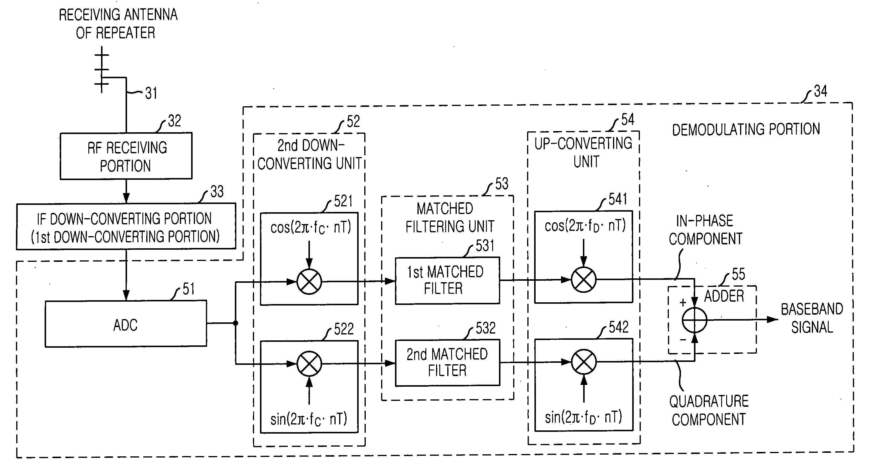
[0046]FIG. 5 is a block diagram illustrating a demodulating portion that can reduce time delay in an on-channel repeater in accordance with an embodiment of the present invention. Referring to FIG. 5, the demodulating portion 34 suggested in the present invention includes an analogue-to-digital conversion unit (ADC) 51, a second down-converting unit 52, a matched filtering unit 53, an up-converting unit 54, and an adder 55.

[0047] The ADC 51 converts analogue intermediate frequency (IF) signals to digital IF signals, when the radio frequency (RF) broadcasting signals transmitted from a main transmitter 21 through a receiving antenna 31 of on-channel repeaters and an RF receiving portion 32 are inputted after down-converted in an IF down-converting portion 33, which is a first down-convert...


PUM


Abstract

Provided is a demodulation apparatus capable of reducing time delay of an on-channel repeater in a terrestrial digital television (TV) broadcasting system and a demodulation method thereof. The demodulation method includes the steps of a) converting an analogue intermediate frequency (IF) signal into a digital IF signal; b) generating an in-phase (I) signal and a quadrature (Q) signal by converting the frequency of the digital IF signals and down-converting the frequencies of the pilot components of the I and Q signals so that the center frequencies of the I and Q signals could be shifted to 0; c) filtering the down-converted I and Q signals and maximizing signal-to-noise ratio; d) up-converting the filtered I and Q signals into baseband signals in which the center frequencies of the filtered I and Q signals are placed in baseband and shifting the frequency of the pilot components of the filtered I and Q signals to 0; and e) adding up the up-converted I and Q signals to restore the signals into baseband signals for broadcasting.

Description

FIELD OF THE INVENTION [0001] The present invention relates to a digital television (TV) broadcasting service technology; and, more particularly, to a demodulation apparatus that can reduce time delay of an on-channel repeater (OCR) in a terrestrial digital TV broadcasting system and a method thereof. DESCRIPTION OF RELATED ART [0002] Generally, main transmitters and repeaters are positioned to provide broadcasting services based on the broadcasting coverage of each broadcasting station and the topological surroundings / natural features. [0003] The repeaters are installed in the area where broadcasting signals from a main transmitter are weakly received to solve the broadcasting signal reception problems in the regions which are out of the broadcasting service coverage and to expand the signal transmission area of the main transmitter. [0004] The repeaters that are used to provide the current terrestrial digital broadcasting services receive broadcasting signals from the main transmi...

Claims


Application Information

Patent Timeline
Patent Type & Authority Applications(United States)
IPC IPC(8): H04N7/015H04B1/10H04H20/06H04L27/06H04L27/14H04N5/21H04N5/38H04N5/455
CPCH04H20/06H04B7/15564H04N5/38H04N5/211H04N7/015
Inventor PARK, SUNG-IKLEE, YONG-TAESEO, JAE-HYUNKIM, SEUNG-WONLEE, SOO-IN
Owner ELECTRONICS & TELECOMM RES INST
Why Eureka
Try Eureka