Fluid dynamic bearing motor

a dynamic bearing and motor technology, applied in sliding contact bearings, instruments, record information storage, etc., can solve the problems of non-repeatability, noise and vibration, and the inability to allow a higher track density of a hard disk, so as to prevent the conical vibration of the shaft, reduce heat generation and power consumption, and prevent oil leakage

Inactive Publication Date: 2005-05-05
G&W TECH
View PDF1 Cites 4 Cited by
  • Summary
  • Abstract
  • Description
  • Claims
  • Application Information

AI Technical Summary

Benefits of technology

[0049] Since the fluid dynamic bearing motor employs the thrust fluid dynamic bearings on the upper and lower portions of the shaft, conical vibration of the shaft is prevented and heat generation and power

Problems solved by technology

In general, friction between the ball bearings of a motor and shafts causes noise and vibration.
Such vibration can cause a non-repeatable run out (NRRO), which does not allow higher track density of a hard disk.
However, the spindle motor employing the fluid dynamic bearing has the following problems.
However, if the rotating body is excessively tilted, a hydrodynamic pressure change increases, and vibration, such as NRRO, increases.
Second, when the fluid dynamic bearing motor continuously operates, heat is produced.
Furthermore, as the load support force is reduced, a clearance between fluid dynamic bearing surfaces is further narrowed, the

Method used


Image

  • Fluid dynamic bearing motor
  • Fluid dynamic bearing motor
  • Fluid dynamic bearing motor

Examples


Embodiment Construction

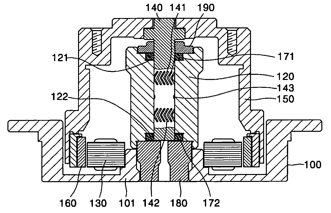
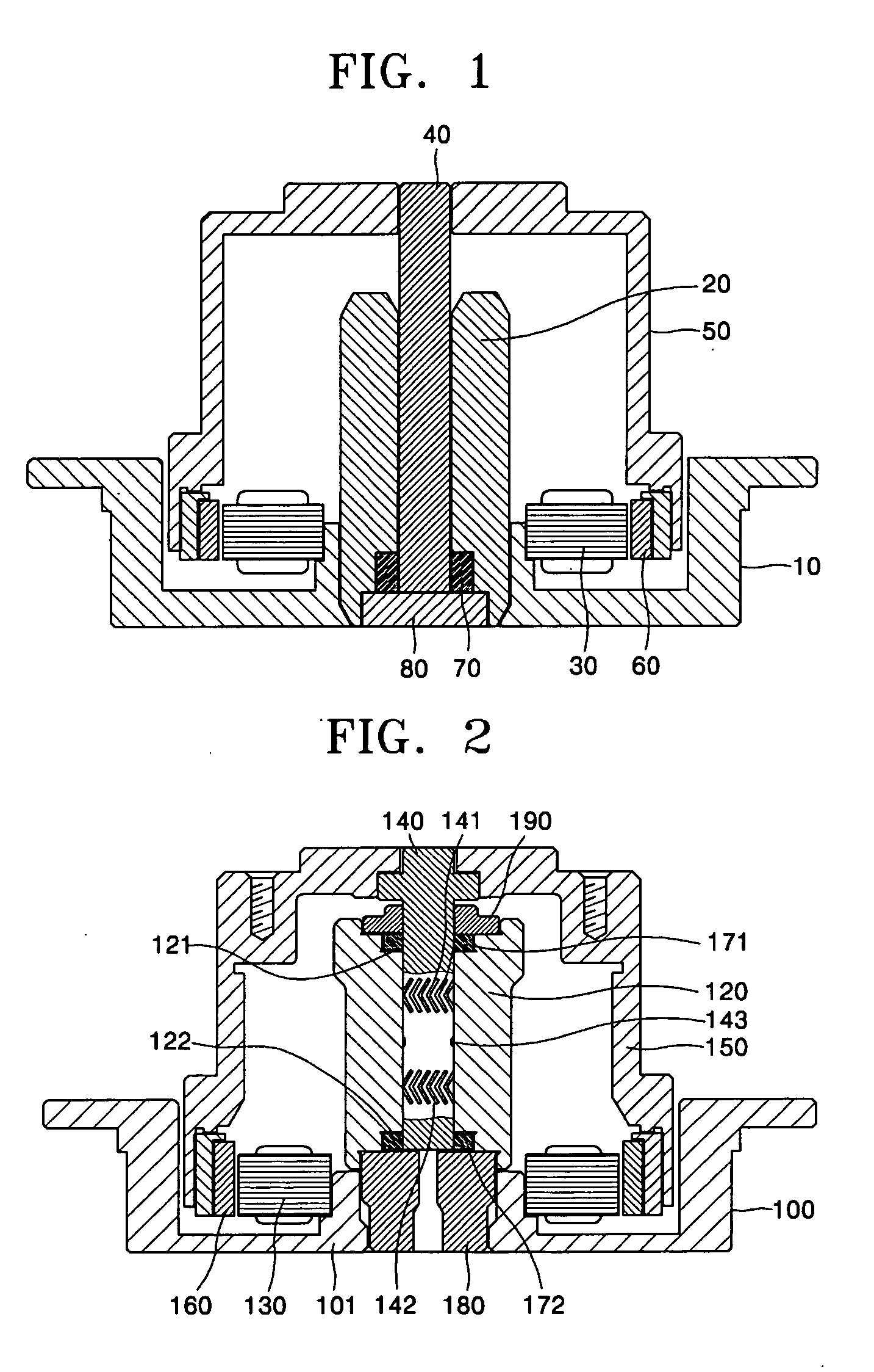
[0065] A fluid dynamic bearing motor employs both a journal fluid dynamic bearing, which is generated at a journal portion of a shaft facing a sleeve, and a thrust fluid dynamic bearing.

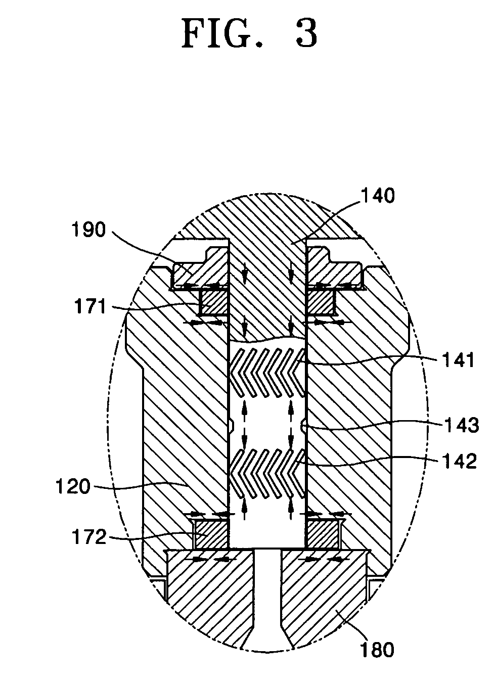
[0066] In particular, the fluid dynamic bearing motor employs one pair of thrust fluid dynamic bearings on upper and lower portions of the shaft. Accordingly, although the fluid dynamic bearing motor has the same load support force as an equivalent motor having one thrust fluid dynamic bearing, the fluid dynamic bearing motor prevents conical vibration of the shaft, and reduces heat generation and power consumption by reducing a speed of a thrust plate, which forms the thrust fluid dynamic bearing, relative to the sleeve.

[0067] Moreover, the fluid dynamic bearing motor has a hydrodynamic pressure cover for producing a hydrodynamic pressure coupled to an upper end portion of the sleeve to which the shaft is rotatably coupled, thereby increasing an internal pressure of a fluid dynamic bearing and eff...


PUM


Abstract

Provided is a fluid dynamic bearing motor that can reduce vibration, oil deterioration, and power consumption by employing at least one pair of thrust bearings on upper and lower portions of a shaft. The fluid dynamic bearing motor includes: a housing to which a core with a coil wound around it, a sleeve having an axial hole at a central portion thereof, and a cover block supporting the sleeve are fixed; a shaft rotatably inserted into the axial hole to form an oil gap with the hole; a hub fixed to an upper end portion of the shaft and having a downwardly extending portion to an inner surface of which a magnet generating an electromagnetic force through an interaction with the core is attached; and circular thrust plates respectively fixed to upper and lower portions of the shaft, wherein receiving grooves are formed on an inner portion of the sleeve and accommodate the thrust plates to form fluid dynamic bearing surfaces. Since the fluid dynamic bearing motor employs the thrust fluid dynamic bearings on the upper and lower portions of the shaft, conical vibration of the shaft is prevented and heat generation and power consumption are reduced. Furthermore, since the fluid dynamic bearing motor employs the hydrodynamic pressure cover, oil leakage is prevented and an internal pressure of the fluid dynamic bearing is enhanced.

Description

BACKGROUND OF THE INVENTION [0001] This application claims the priority of Korean Patent Application Nos. 2003-78039, filed on Nov. 5, 2003 and 2004-44497, filed on Jun. 16, 2004, in the Korean Intellectual Property Office, the disclosures of which are incorporated herein by reference. [0002] 1. Field of the Invention [0003] The present invention relates to a fluid dynamic bearing motor, and more particularly, to a fluid dynamic bearing motor that can reduce vibration, oil deterioration, and power consumption by employing at least one pair of thrust bearings on upper and lower portions of a shaft. Further, the present invention relates to a fluid dynamic bearing motor that has an improved load support force to bear the load of a plurality of platters for recording and / or collecting a great amount of information. [0004] 2. Description of the Related Art [0005] In general, friction between the ball bearings of a motor and shafts causes noise and vibration. Such vibration can cause a n...

Claims


Application Information

Patent Timeline
IPC IPC(8): F16C17/10F16C33/10G11B19/20
CPCF16C17/045F16C17/107F16C2370/12G11B19/2018F16C33/107
Inventor KIM, SANG UK
Owner G&W TECH
Why Eureka
Try Eureka