Apparatus and method for containing and regulating the pressure in a pressure vessel

Inactive Publication Date: 2005-05-05
AOS HLDG CO
View PDF31 Cites 8 Cited by
  • Summary
  • Abstract
  • Description
  • Claims
  • Application Information

AI Technical Summary

Benefits of technology

[0003] The inventors have developed a method for manufacturing a tank that can reduce one or more of these redundant steps. Furthermore, they have developed a tank and a pressure sensing assembly that can be used with said method. For example, some embodiments relate to a method of manufacturing a water storage tank for a well. The method can include one or more steps such as forming a pressure vessel having an opening, an interior volume, and an elastic member located

Problems solved by technology

However, this step also causes

Method used


Image

  • Apparatus and method for containing and regulating the pressure in a pressure vessel
  • Apparatus and method for containing and regulating the pressure in a pressure vessel
  • Apparatus and method for containing and regulating the pressure in a pressure vessel

Examples


Embodiment Construction

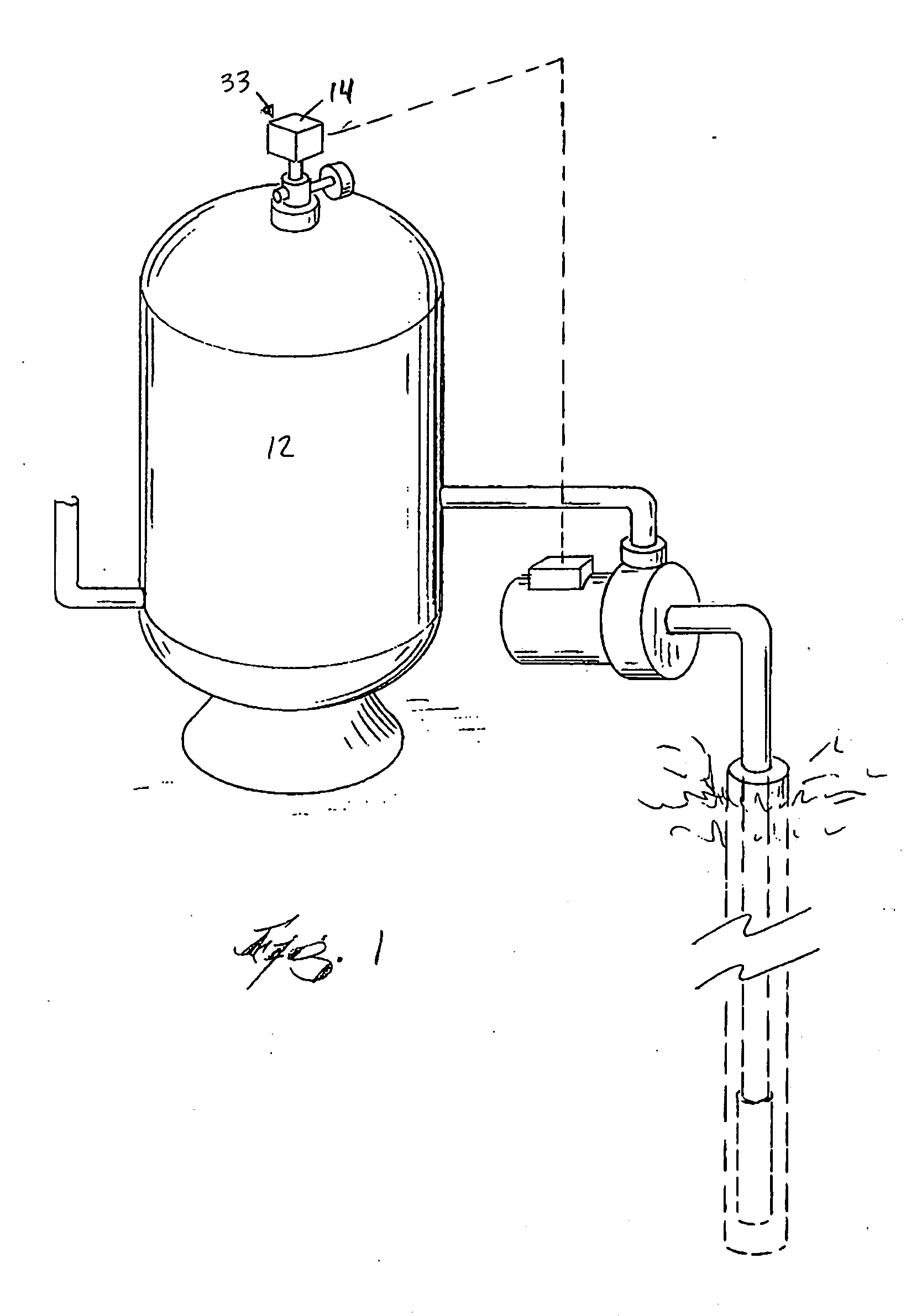
[0022] As illustrated in FIG. 1, a water pressure system for a well generally has a drop pipe extending into a water bearing aquifer, and a pump is used to deliver water from the aquifer to a pressure vessel or storage tank 12. Several types of pumps can be used, such as submersible pumps and non-submersible pumps. Water from the pressure tank 12 can be distributed from the tank for use.

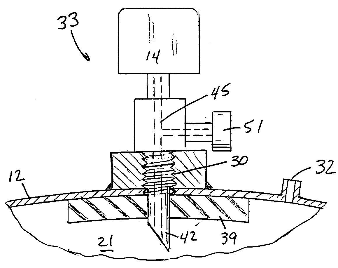
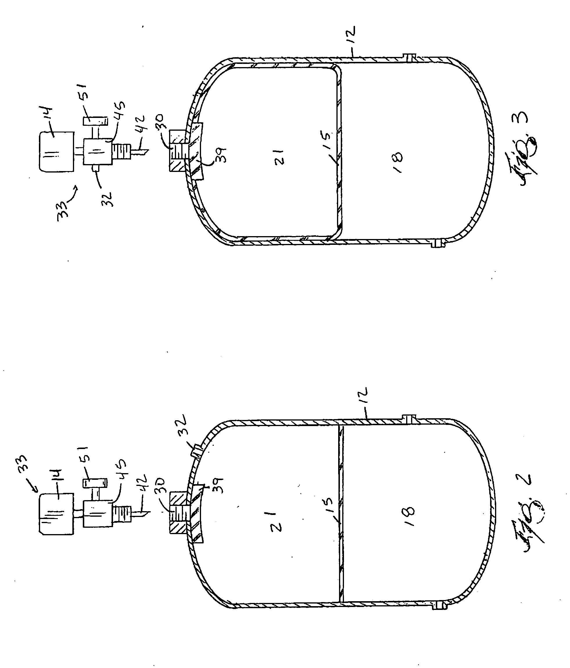
[0023] The pressure tank 12 generally holds a reserve supply of water under pressure within the tank until it is needed. As water is drawn from the tank 12, the pressure within the tank 12 forces the water out of the tank 12 and consequently the pressure gradually decreases. A pressure switch 14 coupled to the tank 12 is used to maintain the pressure within the tank 12 between a preset minimum value and a preset maximum value. Upon reaching the preset minimum pressure, the pressure switch 14 automatically activates the pump. Water is then pumped into the tank 12 to replenish the tank 12 with water a...


PUM


Abstract

Some embodiments relate to an apparatus and method for manufacturing a tank and/or pressure sensing assembly that can reduce one or more steps from a conventional manufacturing operation. The tank of some embodiments can have a seal that is capable of sealing an entire opening within the tank and is adapted to be punctured or pierced by a portion of a pressure sensing assembly or while the pressure sensing assembly is attached to the tank. The pressure sensing assembly of some embodiments can include a conduit connectable with the tank and a pressure switch coupled to the conduit. A projection contiguous with and extending from the conduit can pierce the seal (if used) on the tank. The projection can also pierce an elastic member within the tank in the event that the elastic member contacts the piercing member due to a leak.

Description

BACKGROUND OF THE INVENTION [0001] Some homes and businesses are not served by municipal water services. These homes and businesses generally utilize a private well to solve their water needs. With a private well, water is drawn from a water bearing aquifer in the ground and pumped to a storage tank containing a fixed amount of air. As water enters the tank, the air volume occupied by the air is reduced and the pressure within the tank rises. The tank is therefore a pressure accumulator that delivers water to a faucet or other end use location without requiring the pump to cycle every time water is drawn from the tank. SUMMARY OF THE INVENTION [0002] Some aspects of the present invention are directed toward improving the process of manufacturing and preparing a pressure tank assembly. During conventional manufacturing processes, the pressure tank is generally pressure tested. As part of the pressure test, an air pressure sensing assembly or regulator valve assembly is attached to th...

Claims


Application Information

Patent Timeline
IPC IPC(8): E03B11/02
CPCE03B11/02
Inventor SCHURTER, ROBERT M.CARIAN, STEPHEN
Owner AOS HLDG CO
Why Eureka
Try Eureka