

Depth adjustment for a clamping chuck
- Summary
- Abstract
- Description
- Claims
- Application Information
AI Technical Summary
Benefits of technology
Problems solved by technology
Method used
Image

Examples
Embodiment Construction
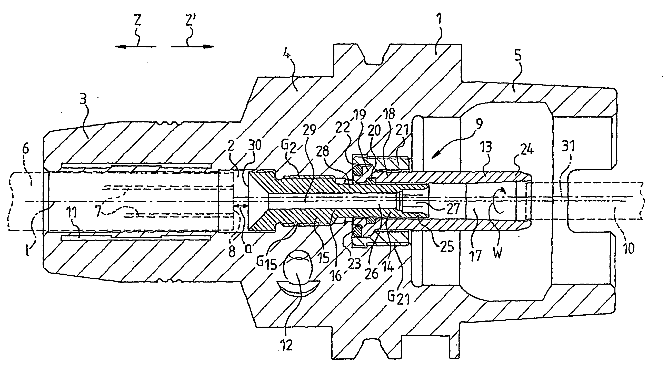
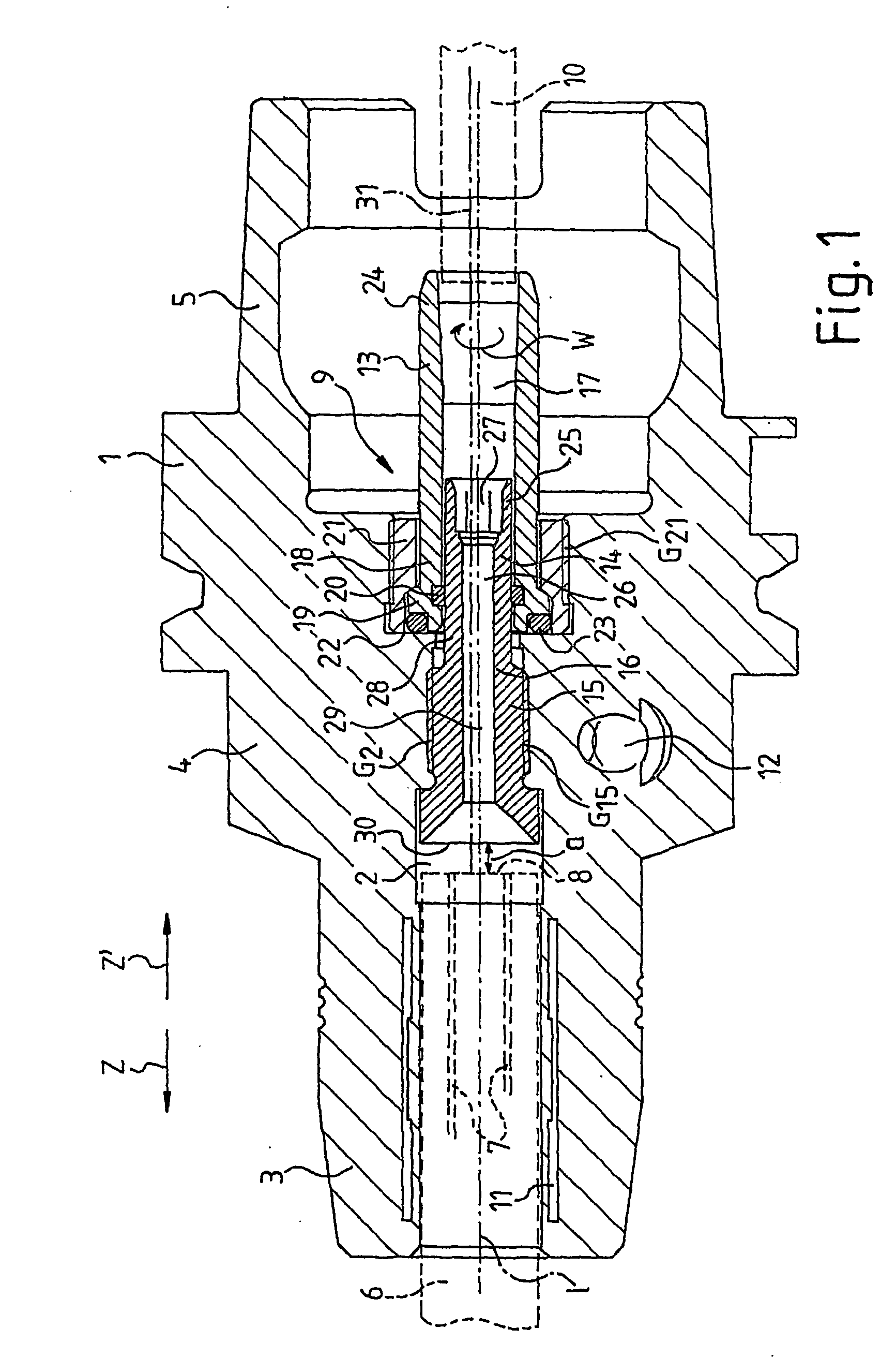
[0028]FIG. 1 shows a section of a clamping chuck 1. The clamping chuck 1 comprises a longitudinal axis 1. Along the longitudinal axis 1, a borehole 2 passes through the clamping chuck 1, wherein the diameter of said borehole 2 differs in some sections. The clamping chuck 1 comprises a clamping section 3, a middle section 4 and a coupling section 5. The clamping section 3 is designed to accommodate a tool 6 (indicated by dashed lines) which comprises feeding channels 7 for conveying coolant or lubricant to a tool tip (not shown), which feeding channels 7 lead to a bottom surface 8. Arranged in the middle section 4 in the borehole 2 is a device 9 for supplying a coolant or lubricant to the feeding channels 7 of the tool 6. By way of the coupling section 5, the clamping chuck 1 is coupled to a spindle (not shown) of a machine tool (not shown), wherein the coolant or lubricant is supplied by the spindle to the device 9 by way of a line 10 (shown by a dashed line). The clamping chuck 1 i...
PUM
| Property | Measurement | Unit |
|---|---|---|
| Diameter | aaaaa | aaaaa |
| Shape | aaaaa | aaaaa |
Abstract
Description
Claims
Application Information