
Method and apparatus for maintaining hydraulic pressure when a vehicle is stopped

a technology for maintaining hydraulic pressure and vehicles, which is applied in the direction of positive displacement liquid engines, gearings, fluid couplings, etc., can solve the problems of wasting power or putting excess wear or stress on the hydraulic pump and system, inadequate capacity to provide, and the inability of the hydraulic pump to deliver adequate hydraulic pressure or fluid flow at the lower end of the engine operating rang

Inactive Publication Date: 2005-05-05
ZF FRIEDRICHSHAFEN AG
View PDF4 Cites 35 Cited by
  • Summary
  • Abstract
  • Description
  • Claims
  • Application Information

AI Technical Summary

Benefits of technology

[0001] The present invention is related to a system and a method for maintaining hydraulic pressure in a vehicle hydraulic system when the vehicle i

Problems solved by technology

A common problem in vehicle hydraulic systems, however, is in providing and maintaining the necessary levels of hydraulic pressure and hydraulic fluid flow over the full range of operating conditions, that is, when the vehicle is stopped or is otherwise idling as well as when the engine is operating at full power.
As a consequence, however, it is very common that the hydraulic pump will not deliver adequate hydraulic pressure or fluid flow at the lower end of the engine operating range, such as when the vehicle is stopped and the engine is thereby idling, or when the engine is idling for any other reasons, such as when the vehicle is coasting or running downhill or at engine start-up.
At the other extreme, when the engine is operating in its upper range the hydraulic pump may generate more pressure and fluid flow than is needed or than is safe when the engine is running at the top end of its range, thereby wasting power or putting excess wear or stress on the hydraulic pump and system, even if only for relatively short periods, or may itself be of inadequate capacity to provide the necessary pressure and fluid flow.
While this method is generally operable, it does require an additional power source and the mechanisms and systems necessary to control the secondary power source and pump, with the resulting increase in cost, complexity and weight.

Method used


Image

  • Method and apparatus for maintaining hydraulic pressure when a vehicle is stopped
  • Method and apparatus for maintaining hydraulic pressure when a vehicle is stopped
  • Method and apparatus for maintaining hydraulic pressure when a vehicle is stopped

Examples


Embodiment Construction

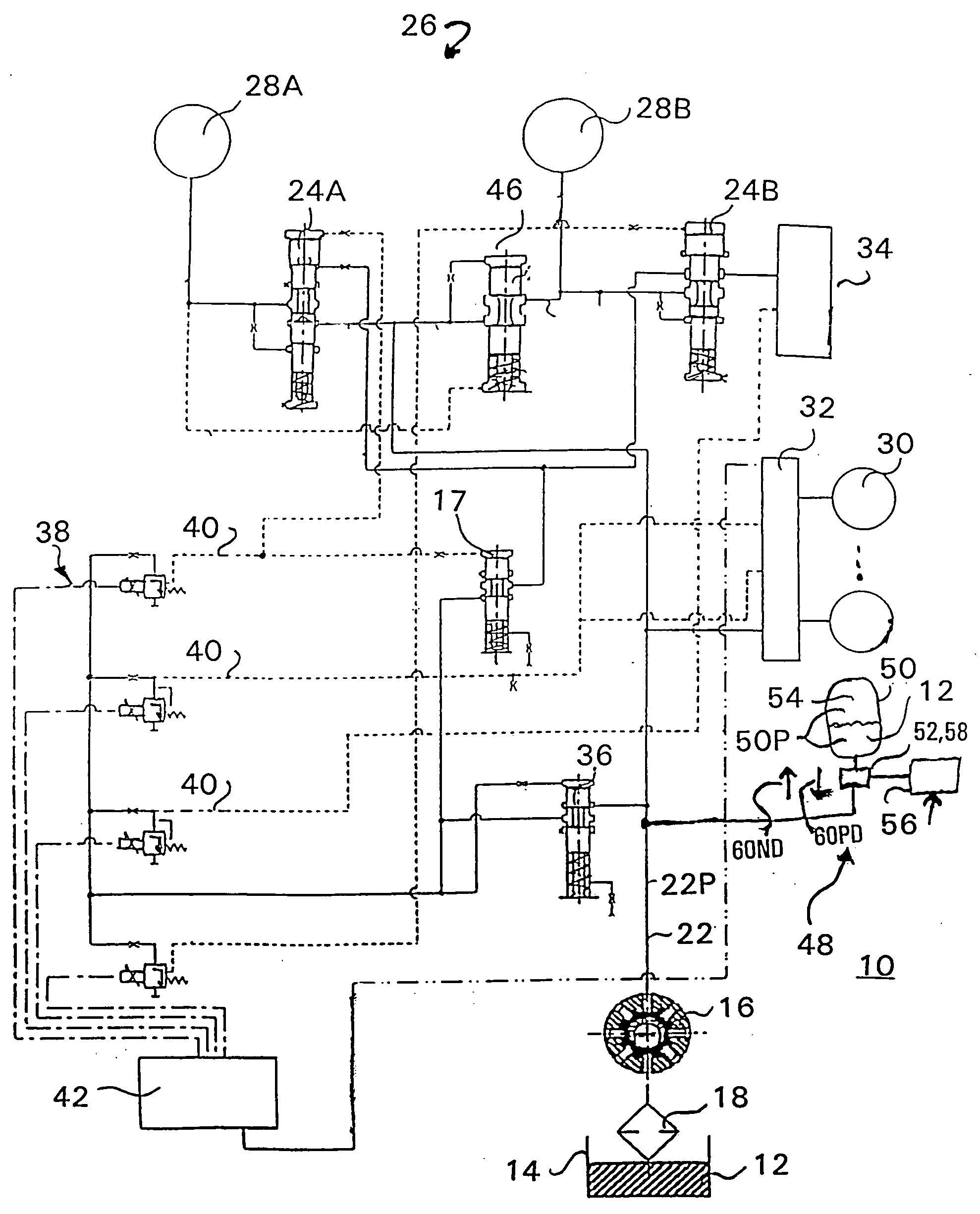
[0021] Referring to FIG. 1, therein is illustrated a simplified exemplary Hydraulic System 10 for a CVT (Continuously Variable Transmission) of a motor vehicle. As indicated there, and in general, Hydraulic Fluid 12 is drawn from a Hydraulic Fluid Sump 14 by a Hydraulic Fluid Pump 16 and through a Hydraulic Fluid Filter Device 18 wherein Hydraulic Fluid Pump 16 may be, for example, a radial piston pump, and Hydraulic Fluid Filter Device 18 may be a suction filter. Hydraulic Fluid 12 is then distributed to the hydraulic elements of Hydraulic System 10 through a Primary Circuit 22 and at a Primary Pressure 22P.

[0022] Primary Circuit 22 provides Hydraulic Fluid 12 to the control and actuation valves of the vehicle transmission, indicated in FIG. 1 as Valve Mechanisms 24A and 24B of Transmission 26 wherein Transmission 26 is assumed, for purposes of the present discussion, to be a CVT having Valve Mechanisms 24A and 24B respectively controlling Primary Pulley Set 28A and a Secondary Pu...


PUM


Abstract

A system for maintaining hydraulic pressure in a vehicle hydraulic system when the vehicle is stopped or idling. A hydraulic pressure reserve system includes a primary hydraulic circuit that includes a hydraulic pump and a hydraulic sump and that provides hydraulic pressure to at least a hydraulically actuated transmission and an accumulator tank and control valve connected from the primary hydraulic circuit for storing a reserve of hydraulic fluid at an accumulator pressure. An accumulator control valve, such as a bi-directional valve, allows a flow of hydraulic fluid between the primary circuit and the accumulator tank according to the primary circuit pressure to raise the primary circuit pressure towards a desired pressure. The hydraulic pressure reserve system may include a primary gear connected from a primary drive and driving an auxiliary secondary gear with a primary drive clutch for connecting the secondary gear to drive the hydraulic pump and an auxiliary drive clutch for connecting the auxiliary secondary gear or a drive chain to drive the hydraulic pump.

Description

CROSS REFERENCES TO RELATED APPLICATIONS FIELD OF THE INVENTION [0001] The present invention is related to a system and a method for maintaining hydraulic pressure in a vehicle hydraulic system when the vehicle is stopped or idling and, in particular, for maintaining hydraulic pressure for the vehicle transmission system when the vehicle is stopped or idling. BACKGROUND OF THE INVENTION [0002] Hydraulically driven and controlled systems are commonly used in vehicle for a range of vehicle systems and functions. A common example of such is a vehicle transmission system, but the vehicle hydraulics systems may include a variety of other systems, such as the brake system or an adaptive suspension system. Also, certain vehicle systems may be integrated, at least with regard to a common, central system for providing hydraulic pressure to a number of hydraulically powered or controlled systems. For example, the hydraulic system for a transmission may also provide hydraulic power for the veh...

Claims


Application Information

Patent Timeline
IPC IPC(8): F04B49/00F15B1/02F16H31/00F16H61/00
CPCF15B1/024F16H61/0021F16H2061/305F16H2312/14F16H2061/0034
Inventor BROWN, TODDSOMMER, STEFANMOZER, HEBERT
Owner ZF FRIEDRICHSHAFEN AG
Features
  • Generate Ideas
  • Intellectual Property
  • Life Sciences
  • Materials
  • Tech Scout
  • Unparalleled Data Quality
  • Higher Quality Content
  • 60% Fewer Hallucinations
Learn More