
Non-leakage balance oil cylinder in power failure

A balancing oil cylinder, no leakage technology, applied in metal processing machinery parts, maintenance and safety accessories, metal processing equipment, etc., can solve the problems of slow sliding of the ram, small balance force, in-situ change of the machine ram, etc., to make up for The effect of oil pressure loss, reliable and permanent pressure compensation

Active Publication Date: 2013-03-20
JIANGSU HENGLI MACHINE TOOL
View PDF6 Cites 0 Cited by
  • Summary
  • Abstract
  • Description
  • Claims
  • Application Information

AI Technical Summary

Problems solved by technology

[0005] 1. It takes a certain amount of time for the motor brake to hold the motor shaft tightly after the machine tool is powered off, and it also takes a certain amount of time for the cut-off valve to cut off the oil circuit. During this process, part of the oil will flow back into the oil tank, and the pressure of the oil cylinder will drop to a certain extent. , so that the balance force is lost. In this way, when the motor brake hugs the motor shaft, the ram will still have a certain amount of down due to its own weight, and the tool will damage the surface of the workpiece.
[0006] 2. When the machine tool is in a state of long-term power failure, the structure of the stop valve in the balance oil circuit determines that there is always a small amount of leakage, so that the oil pressure of the balance oil cylinder will continue to drop, and the balance force will become smaller and smaller, which will cause The ram continues to slide slowly, which changes the original position of the ram of the machine tool, which brings great inconvenience and safety hazards to the subsequent use of the machine tool
Although an accumulator can be added to the balance oil circuit to supplement the pressure of the hydraulic oil, it still cannot fundamentally solve the problem

Method used


Image

  • Non-leakage balance oil cylinder in power failure

Examples


Embodiment 1

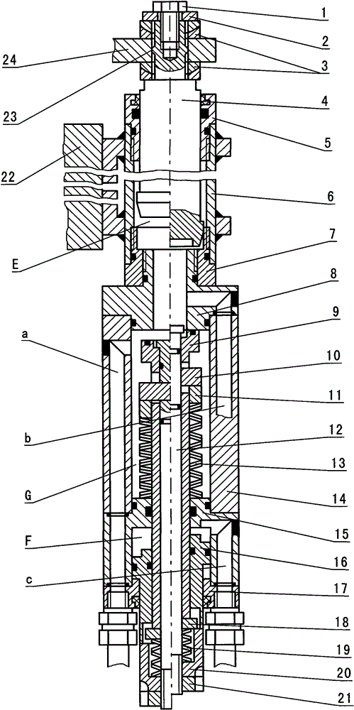
[0023] The invention consists of a balance oil cylinder and a compensating device.

[0024] The balance oil cylinder comprises an oil cylinder barrel 6, a piston rod 4, front and rear end covers 5,7 of the oil cylinder. The oil cylinder barrel 6 is connected and fixed with the machine tool slide plate 22, the piston rod 4 is connected with the machine tool ram connecting plate 24, and the two ends of the oil cylinder barrel 6 are respectively threaded to connect the front and rear covers 5,7 of the balance oil cylinder. The piston rod 4 is fixedly connected with the machine tool ram connecting plate 24 through the bolt 1 at the axial end of the piston rod 4 , the retaining ring 2 and two spherical washers 3 . The end shaft of the piston rod 4 has a matching small ring surface 23, and the two sides of the machine tool ram connecting plate 24 are connected together by two sets of spherical washers 3, and the matching small ring surface 23 of the small shaft on the piston rod 4 a...

Embodiment 2

[0035] This embodiment is a simplification of the compensating device in the first embodiment above, and the pressure supplement mechanism in the compensating device is omitted. That is, the push block 10, the push ring 11, the retaining ring 18 and the small spring 19 are canceled, and the blocking rod 9 and the push rod 12 are made into a whole. 20 can be shortened or eliminated, which can reduce the number of parts, simplify the structure, reduce costs and improve reliability. It is used in occasions that do not require high ram down-jump control.

[0036] The compensating device in this embodiment is composed of a compensating oil cylinder 15, an annular piston 16, a push rod 12, a large spring 13, an intermediate cylinder 14 and a nut 21, and the push rod 12 is placed in the intermediate cylinder 14 and connected with the compensation cylinder 15 In the cavity; the large spring 13 is directly placed on the push rod 12 and placed in the spring chamber G of the middle cyli...


PUM


Abstract

The invention relates to a non-leakage balance oil cylinder in power failure, consisting of a balance oil cylinder and a compensation device. The compensation device consists of a compensation oil cylinder body 15, a piston 16, a push rod 12, a plug rod 9, a big spring 13, a small spring 19, a middle cylinder 14 and a limit sleeve 20, wherein the plug rod 9 is sleeved outside the push rod 12, and is arranged between the middle cylinder 14 and the compensation oil cylinder body 15; the big spring 13 is sleeved on the plug rod 9 in the middle cylinder 14; the piston 16 is sleeved on the plug rod 9 in the compensation oil cylinder body 15; and the small spring 19 and the limit sleeve 20 are arranged on the tail of the push rod 12. The non-leakage balance oil cylinder has the advantages that after a machine tool has a power failure, the compensation device immediately seals an oil cavity E of the balance oil cylinder under the action of the two springs to keep the pressure of hydraulic oil in the balance oil cavity E; and at the same time, the balance oil cylinder is compressed to compensate pressure and make up the pressure loss thereof so as to ensure the balance oil cylinder still leads a ram cannot slide down even the machine tool is powered off for long term.

Description

technical field [0001] The invention relates to a component of a CNC machine tool gantry machining center, in particular to a power-off non-leakage balance oil cylinder. Background technique [0002] The gantry machining center is used for rough and fine machining of large parts. It has the characteristics of strong load-bearing capacity, large stroke, and high precision. One process, and can also perform three-dimensional processing on large molds, with high efficiency and good processing accuracy. The spindle head of the gantry machining center is installed at the lower end of the ram, and the ram is placed inside the slide plate. The servo motor moves up and down along the guide rail through the ball screw drive to complete the Z-axis cutting and processing feed. Since the Z-axis feed of the ram is in the vertical downward direction, the self-weight of the ram, the spindle head and the transmission mechanism is in the same direction as the Z-axis feed force, but opposite...

Claims


Application Information

Patent Timeline
Patent Type & Authority Patents(China)
IPC IPC(8): B23Q11/00
Inventor 孙德洲许兴旺葛东升
Owner JIANGSU HENGLI MACHINE TOOL
Features
  • Generate Ideas
  • Intellectual Property
  • Life Sciences
  • Materials
  • Tech Scout
  • Unparalleled Data Quality
  • Higher Quality Content
  • 60% Fewer Hallucinations
Learn More