
Systems and methods for correcting high order aberrations in laser refractive surgery

a laser refractive surgery and high-order aberration technology, applied in laser surgery, medical science, surgery, etc., can solve the problems of high-order aberration, aberration of the optical system, refractive or visual errors,

Active Publication Date: 2005-05-05
AMO MFG USA INC
View PDF31 Cites 30 Cited by
  • Summary
  • Abstract
  • Description
  • Claims
  • Application Information

AI Technical Summary

Benefits of technology

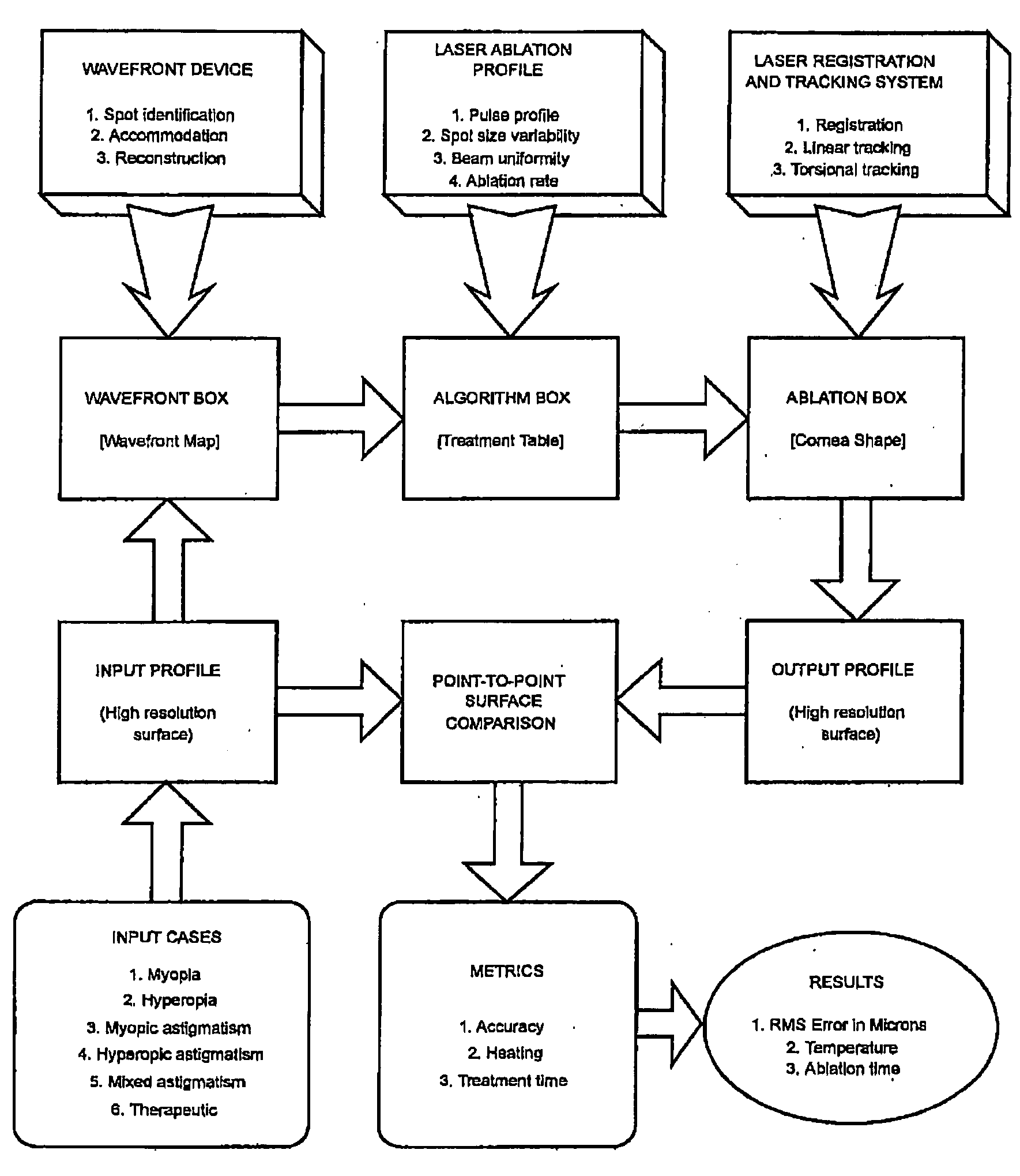
[0007] The present invention provides a novel approach to evaluating and improving refractive surgery systems. Further, the present invention provides novel approaches to error source control and adjustment or optimization of ablation profiles or other optical data, for addressing high order aberrations. Relatedly, the present invention provides a novel simulation approach to identifying and characterizing system factors that can contribute to, or that can be adjusted to inhibit, optical aberrations. What is more, the present invention provides an approach to modeling limitations on system components so that adjustment of the system parameters such as, for example, the accuracy of registration, the accuracy of fitting in the ablation algorithm, the tracker speed, the accuracy and system latency time of tracking, and / or the laser beam uniformity and variability can be obtained for a certain level of high order aberration correction.

Problems solved by technology

These deviations, or aberrations, include imperfections, irregularities, or distortions of the optical quality of the eye, and can lead to refractive or visual errors.
High order aberrations, on the other hand, are aberrations of the optical system that go beyond nearsightedness, farsightedness, and astigmatism.
Such aberrations are typically not corrected with glasses or contact lenses.
However, current systems and methods may be less than ideal, and may even introduce or amplify high order aberrations.

Method used


Image

  • Systems and methods for correcting high order aberrations in laser refractive surgery
  • Systems and methods for correcting high order aberrations in laser refractive surgery
  • Systems and methods for correcting high order aberrations in laser refractive surgery

Examples


Embodiment Construction

[0067] The present invention can be readily adapted for use with existing laser systems, wavefront measurement systems, and other optical measurement devices. While the systems, software, and methods of the present invention are described primarily in the context of a laser eye surgery system, it should be understood the present invention may be adapted for use in alternative eye treatment procedures and systems such as spectacle lenses, intraocular lenses, contact lenses, corneal ring implants, collagenous corneal tissue thermal remodeling, and the like.

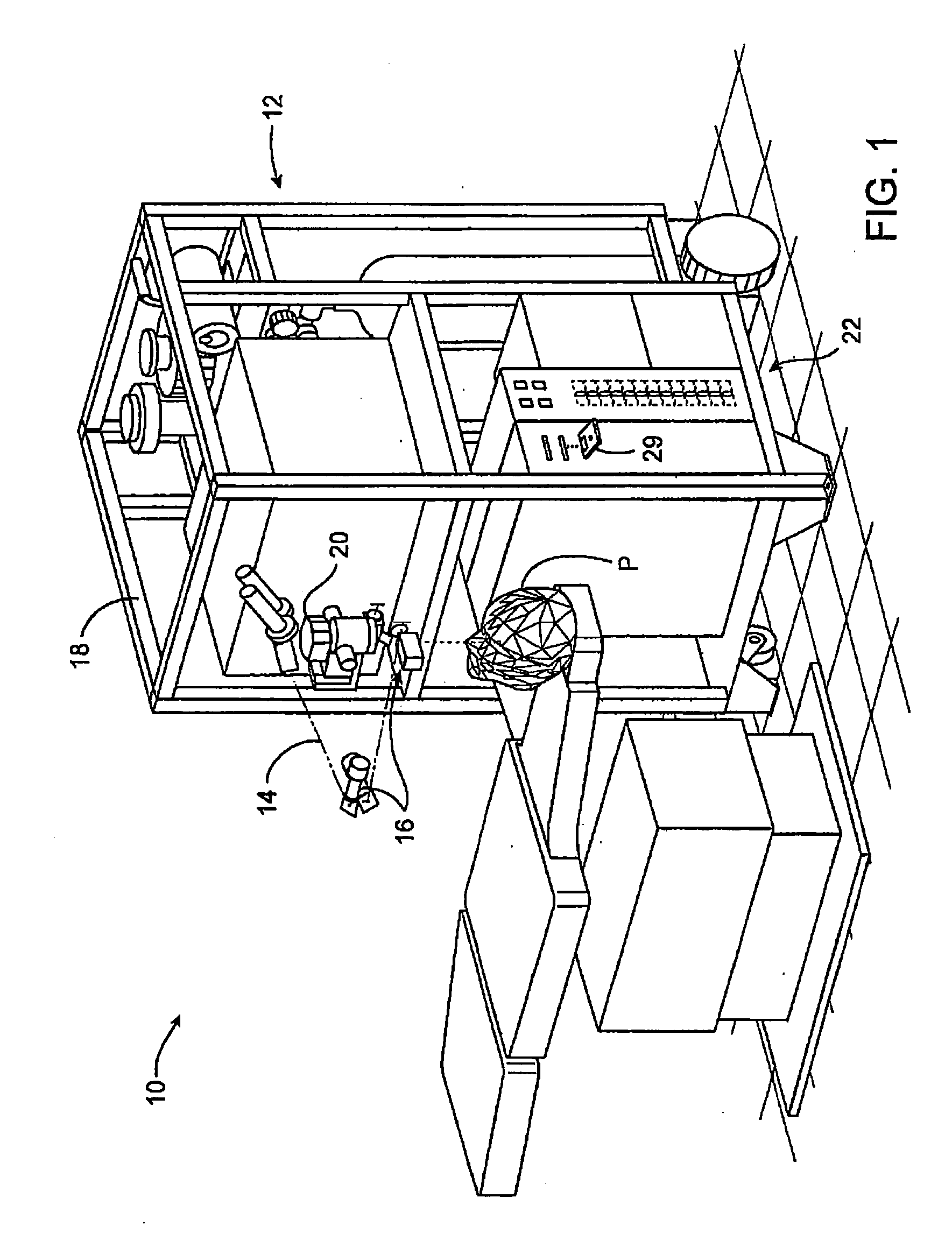
[0068] Turning now to the drawings, FIG. 1 illustrates a laser eye surgery system 10 of the present invention, including a laser 12 that produces a laser beam 14. Laser 12 is optically coupled to laser delivery optics 16, which directs laser beam 14 to an eye E of patient P. A delivery optics support structure (not shown here for clarity) extends from a frame 18 supporting laser 12. A microscope 20 is mounted on the delivery optics...


PUM


Abstract

Optical correction methods, devices, and systems reduce optical aberrations or inhibit refractive surgery induced aberrations. Error source control and adjustment or optimization of ablation profiles or other optical data address high order aberrations. A simulation approach identifies and characterizes system factors that can contribute to, or that can be adjusted to inhibit, optical aberrations. Modeling effects of system components facilitates adjustment of the system parameters.

Description

BACKGROUND OF THE INVENTION [0001] This invention generally relates to optical correction, and in particular provides methods, devices, and systems that reduce optical aberrations or inhibit refractive surgery induced aberrations. [0002] To some degree, all eyes deviate from a perfect optical system. These deviations, or aberrations, include imperfections, irregularities, or distortions of the optical quality of the eye, and can lead to refractive or visual errors. Aberrations can be classified into low order and high order aberrations, and can be described mathematically, for example, by Zernike polynomials. [0003] Low order aberrations include prismatic, spherical, and cylindrical errors. First order, or prismatic, errors include vertical prism and horizontal prism errors. Second order, or defocus and astigmatism, errors include myopia, hyperopia, 45 / 135 astigmatism, and 90 / 180 astigmatism, for example. Traditional forms of optical correction involve measuring low order aberration...

Claims


Application Information

Patent Timeline
IPC IPC(8): A61F9/008A61F9/01
CPCA61F9/008A61F9/00806A61F9/00817A61F2009/00844A61F2009/00897A61F2009/00848A61F2009/00857A61F2009/00872A61F2009/0088A61F2009/00846
Inventor DAI, GUANGMINGLIANG, JUNZHONG
Owner AMO MFG USA INC
Learn More