Transformer performance prediction

a transformer and performance prediction technology, applied in the direction of instruments, nuclear elements, nuclear engineering, etc., can solve the problems of power loss to a single house, power loss to a large number of customers, and power loss to a number of customers

Inactive Publication Date: 2005-05-05
ABB RES LTD
View PDF12 Cites 44 Cited by
  • Summary
  • Abstract
  • Description
  • Claims
  • Application Information

AI Technical Summary

Benefits of technology

[0008] A method for predicting transformer performance includes receiving information representative of a plurality of built transformers, the information comprising a design specification for each built transformer, and measured test information for each built transformer, receiving a second transformer design specification, and determining, via an intelligent system, a predicted test result for the second transformer design specification based on the second transformer design specification and the information representative of the plurality of built transformers.

Problems solved by technology

Failure of a power transformer often means power loss to a number of customers.
A failure of a large substation power transformer may mean power loss to a large number of customers while failure of a small pole-mounted power transformer may mean power loss to a single house.
In addition to transformer reliability, electric utilities are typically very concerned with power transformer cost and efficiency.
While the initial purchase cost is generally an important consideration in any purchase, power transformers also have annual costs to run the transformer due to internal losses associated with each transformer.
Moreover, electric utilities often negotiate a contractual financial penalty from transformer manufacturers if a transformer does not meet the specified efficiency.
Power transformer design, however, is a very complex process.
In reality, however, many other design parameters may affect the eddy current losses.
Conventional techniques do not address the effect of these other design parameters and the unknown relationships between parameters.

Method used


Image

  • Transformer performance prediction
  • Transformer performance prediction
  • Transformer performance prediction

Examples


Embodiment Construction

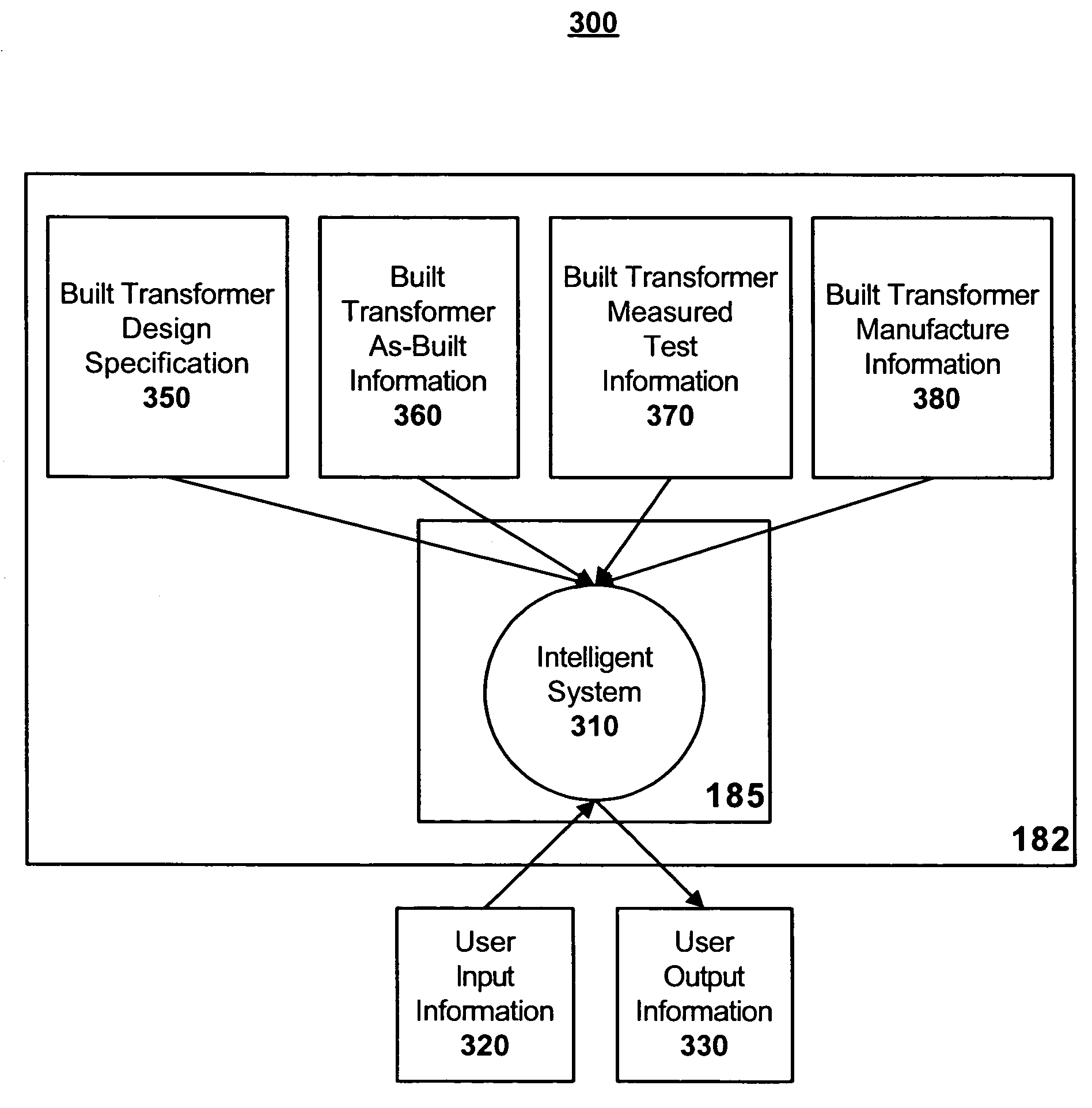
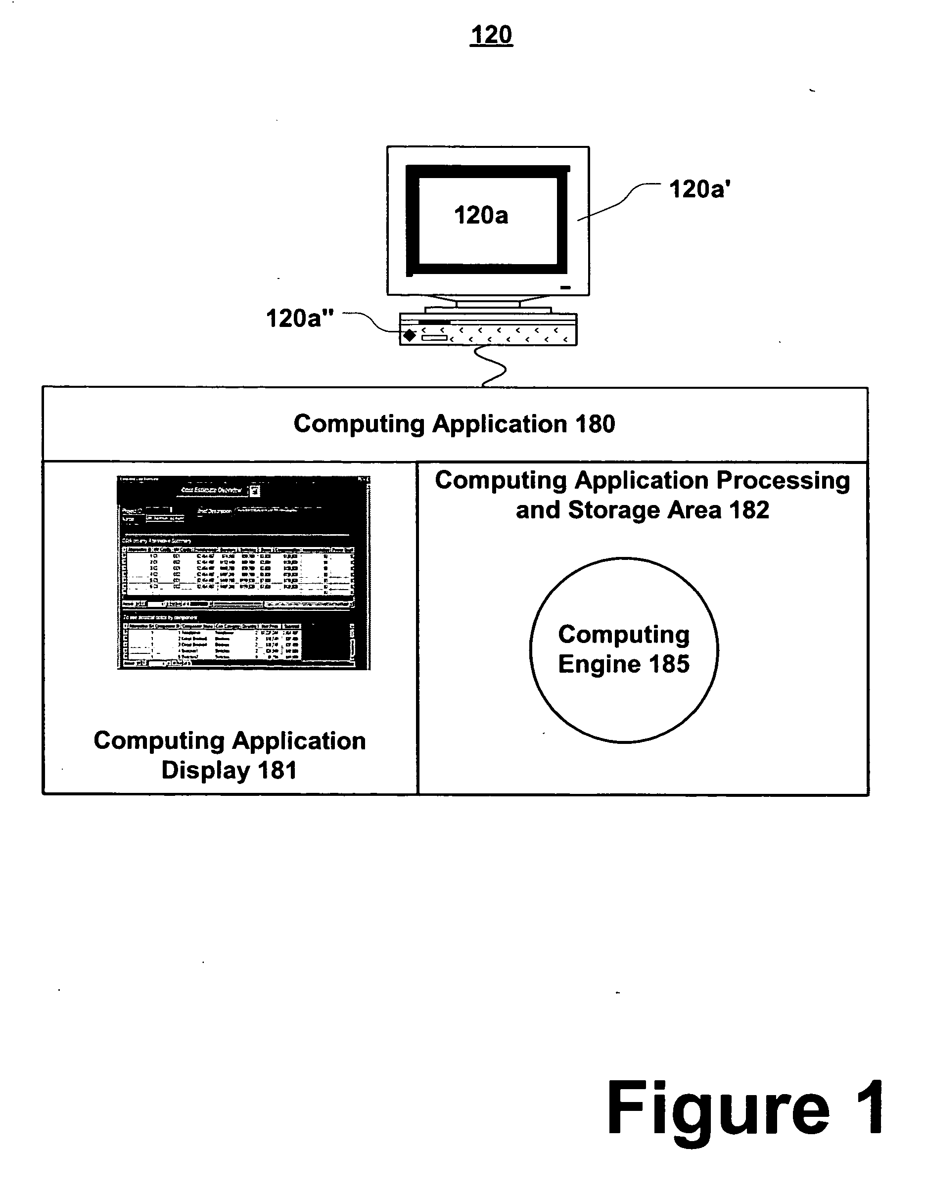
[0019] Transformer performance is predicted using an intelligent system based on a transformer design and test results of previously built transformers. Systems and methods for predicting transformer performance may be implemented in one or more of the exemplary computing environments described in more detail below, or in other computing environments.

[0020]FIG. 1 shows computing system 120 that includes computer 120a. Computer 120a includes display device 120a′ and interface and processing unit 120a″. Computer 120a executes computing application 180. As shown, computing application 180 includes a computing application processing and storage area 182 and a computing application display 181. Computing application processing and storage area 182 includes computing engine 185. Computing engine 185 may implement systems and methods for predicting transformer performance. Computing application display 181 may include display content which may be used for predicting transformer performanc...


PUM


Abstract

A method for predicting transformer performance includes receiving information representative of a plurality of built transformers, the information comprising a design specification for each built transformer, and measured test information for each built transformer, receiving a second transformer design specification, and determining, via an intelligent system, a predicted test result for the second transformer design specification based on the second transformer design specification and the information representative of the plurality of built transformers.

Description

CROSS-REFERENCE TO RELATED APPLICATIONS [0001] This application is related to co-pending patent application Ser. No.______, filed concurrently on Oct. 31, 2003, entitled “Transformer Testing” (Attorney Docket: ABDT-0578 / B030100), which is hereby incorporated by reference in its entirety. This application is related to co-pending patent application Ser. No.______, filed concurrently on Oct. 31, 2003, entitled “Method for Generating and Using a Transformer Model” (Attorney Docket: ABDT-0581 / B030090), which is hereby incorporated by reference in its entirety. This application is related to co-pending patent application Ser. No.______, filed concurrently on Oct. 31, 2003, entitled “Method for Evaluating a Transformer Design” (Attorney Docket: ABDT-0582 / B030080), which is hereby incorporated by reference in its entirety.FIELD OF THE INVENTION [0002] The invention relates generally to predicting transformer performance, and more particularly to using an intelligent system to predict trans...

Claims


Application Information

Patent Timeline
Patent Type & Authority Applications(United States)
IPC IPC(8): G06FG06F11/30G06F15/00G06F15/18G06F17/50G06F19/00G06G7/00G21C17/00
CPCG06F2217/78G06F17/50G06F30/00G06F2119/06
Inventor COX, DAVID N.LONG, THOMAS E.SMILEY, KAREN J.SUTTON, JOHN C.
Owner ABB RES LTD
Why Eureka
Try Eureka