Lane departure prevention apparatus

a technology of lane departure and apparatus, which is applied in the direction of pedestrian/occupant safety arrangements, television systems, instruments, etc., can solve the problems of driver discomfort, driver's will, and it is difficult to conclude that the control of lane departure avoidance is being carried out optimally

Inactive Publication Date: 2005-05-05
NISSAN MOTOR CO LTD
View PDF11 Cites 51 Cited by
  • Summary
  • Abstract
  • Description
  • Claims
  • Application Information

AI Technical Summary

Benefits of technology

[0010] Thus, the present invention was conceived in light of these unsolved problems in the above-described conventional examples. One object of the present invention is to provide a lane departure prevention apparatus in which the control of lane departure can be accomplished without making the driver feel uncomfortable. Another object of the present invention is provide a lane departure prevention apparatus that can conduct departure avoidance control in which control for lane departure avoidance can be carried out optimally. Another object of the present invention is provide a lane departure prevention apparatus that can conduct departure avoidance control in which departure-avoidance control can be performed without causing the driver any discomfort, even when the driver is operating the brakes during lane departure.

Problems solved by technology

Thus, it can hardly be concluded that control for lane departure avoidance is being carried out optimally.
Moreover, with this type of conventional lane departure prevention apparatus, there are situations in which the yaw moment based on the lane departure estimate ends up being imparted to the vehicle even when the driver uses the steering wheel to input steering angle.
When this happens, the vehicle's behavior does not match the operation of the steering wheel, making the driver feel uncomfortable.
However, when information from a camera or other sensor is used to carry out deceleration control, this operation may go against the will of the driver, again making the driver feel uncomfortable.
In other words, with this type of conventional lane departure prevention apparatus, since the yaw moment and deceleration amount applied to the vehicle are determined according to the amount by which the vehicle is estimated to depart from its lane in the future, there is an unresolved problem in that deceleration may be greater than necessary, and the driver may experience some discomfort, when the driver operates the brakes during braking control that includes deceleration control.

Method used


Image

  • Lane departure prevention apparatus
  • Lane departure prevention apparatus
  • Lane departure prevention apparatus

Examples


first embodiment

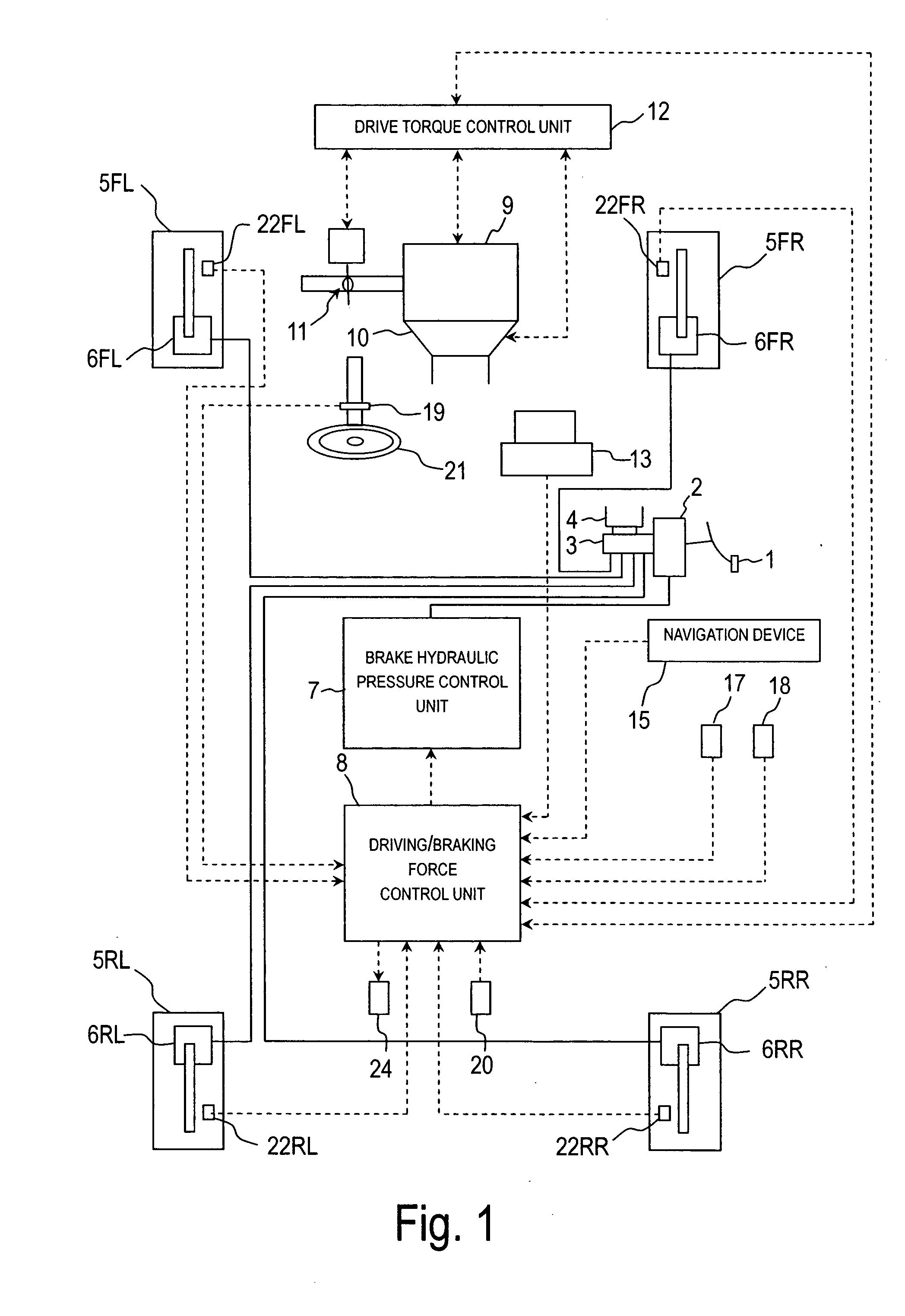
[0045] Referring initially to FIG. 1, a schematic structural diagram of a host vehicle is illustrated that is equipped with a lane departure prevention apparatus in accordance with a first embodiment of the present invention. The embodiment is a rear wheel drive vehicle equipped with the lane departure prevention apparatus of the present invention. This rear-wheel-drive vehicle is equipped with an automatic transmission and a conventional differential gear, and with a braking system that allows independent control of braking force at the front and rear wheels and the left and right wheels.

[0046] In the diagram of FIG. 1, the host vehicle is basically equipped with a brake pedal 1, a booster 2, a master cylinder 3, a reservoir 4, a pair of front wheels 5FL and 5FR, a pair of rear wheels 5RL and 5RR, a pair of front wheel cylinders 6FL and 6FR, a pair of rear wheel cylinders 6RL and 6RR, a brake hydraulic pressure control unit 7, a controller or driving / braking force control unit 8, ...

second embodiment

[0157] Referring now to FIGS. 12 and 13, a vehicle equipped with a lane departure prevention apparatus in accordance with a second embodiment will now be explained. The configuration of the vehicle in this second embodiment is the same as the configuration of the vehicle in the first embodiment (see FIG. 1). In view of the similarity between the first and second embodiments, the parts or steps of the second embodiment that are identical to the parts or steps of the first embodiment will be given the same reference numerals as the parts of the first embodiment. Moreover, the descriptions of the parts or steps of the second embodiment that are identical to the parts or steps of the first embodiment may be omitted for the sake of brevity. In other words, unless otherwise specified, the rest of the configuration of the vehicle in the second embodiment is the same as the configuration of the first embodiment.

[0158] The first embodiment was configured such that no departure-avoidance con...

third embodiment

[0180] Referring now to FIG. 14, a vehicle equipped with a lane departure prevention apparatus in accordance with a third embodiment will now be explained. The configuration of the vehicle in this third embodiment is the same as the configuration of the vehicle in the first embodiment (see FIG. 1). In view of the similarity between the first and third embodiments, the parts or steps of the third embodiment that are identical to the parts or steps of the first embodiment will be given the same reference numerals as the parts or steps of the first embodiment. Moreover, the descriptions of the parts or steps of the third embodiment that are identical to the parts or steps of the first embodiment may be omitted for the sake of brevity. In other words, unless otherwise specified, the rest of the configuration of the vehicle in the third embodiment is the same as the configuration of the first embodiment.

[0181] In the third embodiment, it is determined whether or not control for departur...


PUM


Abstract

A lane departure prevention apparatus is configured to conduct a course correction in a lane departure avoidance direction when the controller 8 determines that there is a potential for a vehicle to depart from a driving lane. The controller 8 combines yaw control and deceleration control to conduct departure prevention control to avoid lane departure. The yaw control is not actuated if the opposite direction from the steering direction coincides with the lane departure direction (steps S10 and S11). Preferably, the controller 8 sets the timing of yaw moment and the deceleration of the vehicle on the basis of the acceleration or deceleration of the vehicle, and performs braking control so that these settings are achieved (steps S7 to S9). Preferably, the controller 8 calculates the target yaw moment in the lane departure-avoidance direction on the basis of the running state of the vehicle, and calculates the deceleration amount by taking into account the driver braking operation amount.

Description

BACKGROUND OF THE INVENTION [0001] 1. Field of the Invention [0002] The present invention relates to a lane departure prevention apparatus. More specifically, the present invention relates to a lane departure prevention apparatus for preventing a host vehicle from departing from a driving lane when such departure seems imminent. [0003] 2. Background Information [0004] Conventional lane departure prevention apparatuses include apparatuses for imparting yaw moment to the host vehicle by controlling the braking force to the wheel and preventing the host vehicle from deviating from the driving lane. These conventional lane departure prevention apparatuses also inform the driver that the host vehicle may possibly depart from the driving lane by providing this yaw moment in cases in which there is a possibility that the host vehicle may depart from a driving lane. For example, one such lane departure prevention apparatus is disclosed in Japanese Laid-Open Patent Publication No. 2000-33860...

Claims


Application Information

Patent Timeline
Patent Type & Authority Applications(United States)
IPC IPC(8): B60R21/00B60T7/22B60T8/1755G08G1/16
CPCB60T7/22B60T8/17557B60T2201/085B60T2201/083B60T2201/08B60R1/00B62D15/029G08G1/167
Inventor SADANO, ONUEMURA, YOSHITAKAOZAKI, MASAHIRO
Owner NISSAN MOTOR CO LTD
Why Eureka
Try Eureka