Expansion valve having solenoid relief valve

Active Publication Date: 2005-05-12
FUJIKOKI CORP
View PDF3 Cites 10 Cited by
  • Summary
  • Abstract
  • Description
  • Claims
  • Application Information

AI Technical Summary

Benefits of technology

[0016] In other words, the present invention provides an assembly in which one relief valve is attached to the side wall of an expansion valve to allow the refrigerant in both the high-pressure and low-pressure circuits to be discharged simultaneously via the one relief valve. The assembly operation of the valve is facilitated since it can be attached to conventional expansion valves.
[0020] According to the present invention, by attaching a single relief valve to the expansion valve which does not require a special connection piping, a means for discharging the refrigerant in the refrigeration cycle rapidly can be realized at a low cost and without having to substantially change the arrangement of the prior art expansion valve.

Problems solved by technology

As mentioned above, according to the prior art refrigeration cycle, it was necessary to dispose two relief valves and piping connections for the valves to the cycle, which caused the cost of the refrigeration cycle to be increased and complicated assembly operations.

Method used


Image

  • Expansion valve having solenoid relief valve
  • Expansion valve having solenoid relief valve
  • Expansion valve having solenoid relief valve

Examples


Embodiment Construction

[0023] The preferred embodiments of the present invention will now be described.

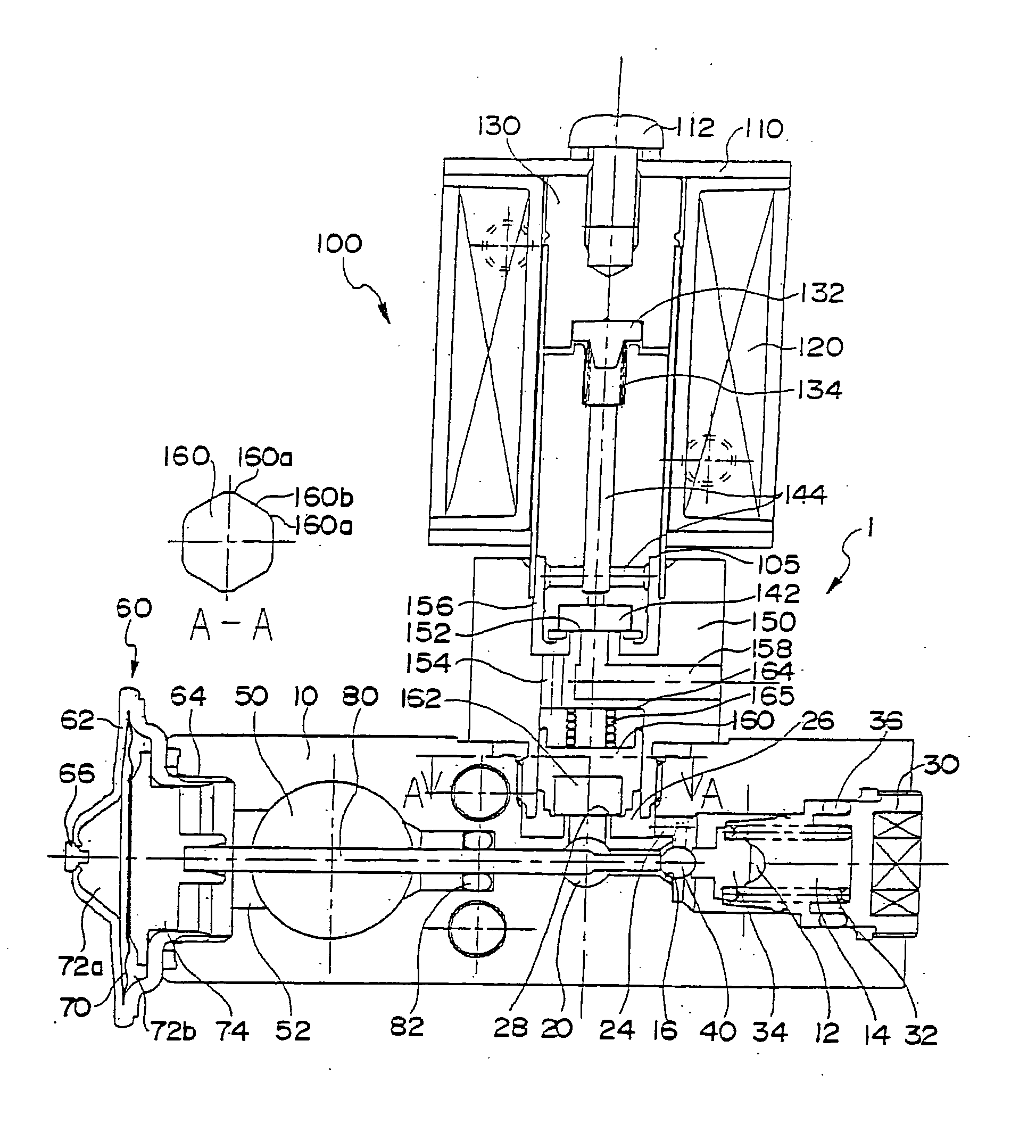
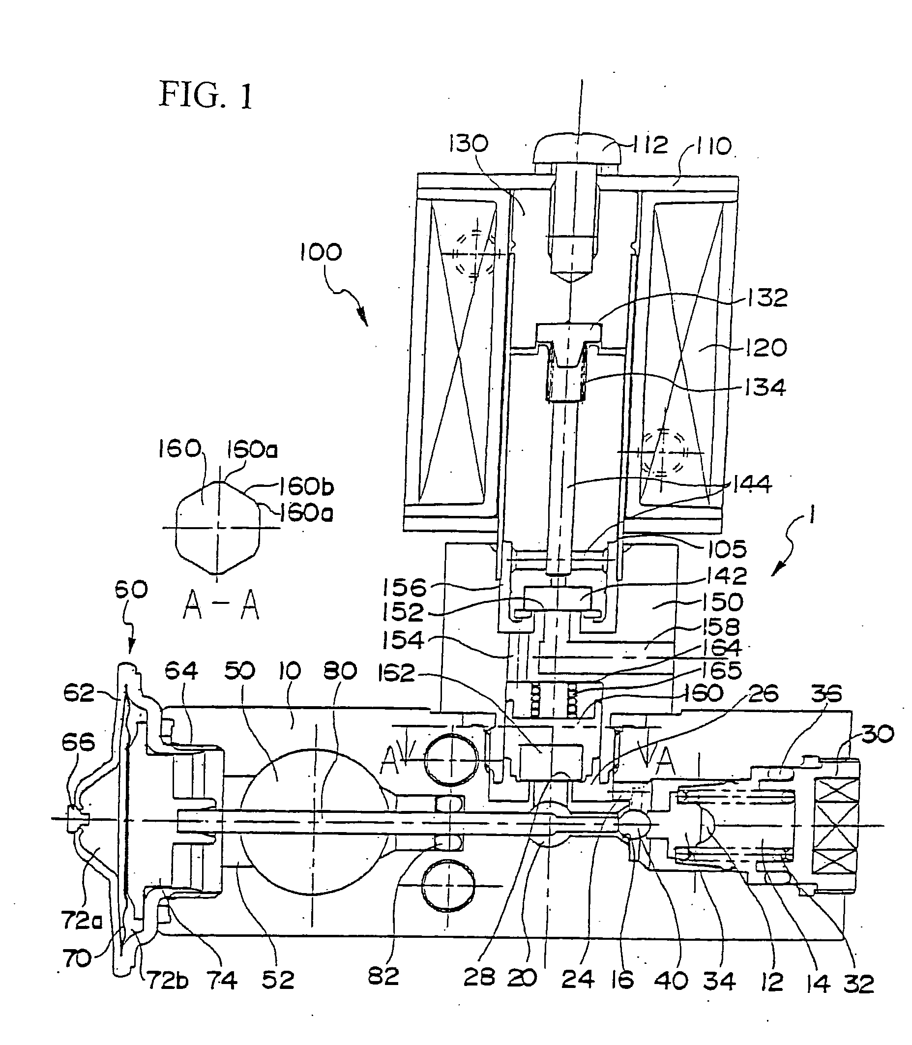
[0024]FIG. 1 is a cross-sectional view of the expansion valve according to the present invention.

[0025] The expansion valve, the entire body of which is denoted by reference number 1, has a valve body 10 which is substantially prismatic. At the lower area of the valve body 10 is formed an inlet 12 through which a liquid-phase refrigerant from a compressor in a refrigeration cycle is supplied, and the inlet 12 is communicated with a valve chamber 14. In the valve chamber 14, a ball-shaped valve means 40 is disposed facing a valve seat 16. The valve means 40 is supported by a spring 32 via a support member 34.

[0026] A nut member 30 is screwed onto an opening portion of the valve chamber 14 and seals the chamber. By tightening the nut member 30, the spring 32 is pre-compressed, and a seal member 36 is attached to the nut member 30 supporting the valve means 40 via the support member 34 with predetermined...


PUM


Abstract

The invention provides an expansion valve equipped to an air conditioning system that has a relief valve for discharging the refrigerant in the system in case of an emergency. An expansion valve 1 controls the flow rate of a refrigerant in a valve chamber 14 into which high-pressure refrigerant is introduced by adjusting the gap between a valve means 40 and a valve seat 16, and sends the refrigerant into a passage 20 leading to an evaporator. A solenoid relief valve 100 has a plunger 140 operated by a magnet coil 120, by which a pilot valve seat 152 of a relief valve body 150 is regularly closed. The high-pressure refrigerant introduced to a relief valve chamber 164 of the relief valve body 150 presses the relief valve means 160, regularly closing the valve of the relief valve seat 28. When electricity is supplied to a coil 120, the plunger 140 is attracted toward an attractor 130 and the pilot valve is opened. The relief valve is also opened so that the refrigerant is discharged through a passage 158 to the atmosphere.

Description

[0001] The present application is based on and claims priority of Japanese patent application No. 2003-376444 filed on Nov. 6, 2003, the entire contents of which are hereby incorporated by reference. BACKGROUND OF THE INVENTION [0002] 1. Field of the invention [0003] The present invention relates to an expansion valve equipped for example to an air conditioner of a vehicle, for controlling the flow rate of a refrigerant sent toward an evaporator, the expansion valve having a mechanism for discharging the refrigerant to the atmosphere in case of an emergency. [0004] 2. Description of the related art [0005] Recently, a refrigerant used in a refrigeration cycle is required to have a property applying small load on the environment. However, some types of refrigerants are harmful to the human body or are inflammable. [0006] In a refrigeration cycle using such types of refrigerant, in case of an emergency such as when the refrigerant is filled in a chamber due to gas leak or when gas leak...

Claims


Application Information

Patent Timeline
IPC IPC(8): F25B41/06F25B49/00
CPCF25B41/062F25B49/005Y02B30/72F25B2341/0683F25B2341/065Y02B30/70F25B41/34F25B41/325F25B41/335F25B41/345
Inventor EZAKI, HIROYUKIWATANABE, KAZUHIKOFUKUDA, EIJI
Owner FUJIKOKI CORP
Why Eureka
Try Eureka