Magnetic screw-holding device

a magnetic screw and screw technology, applied in the field of magnetic screw holding devices, can solve the problems of hand-held adjustment of the magnetic holding device, and achieve the effect of convenient movement, small diameter and easy movemen

Inactive Publication Date: 2005-05-12
FELO WERKZEUGFAB HOLLAND LETZ
View PDF7 Cites 40 Cited by
  • Summary
  • Abstract
  • Description
  • Claims
  • Application Information

AI Technical Summary

Benefits of technology

[0008] The screw-holding device according the present invention comprises a permanent magnet—called a magnet herein—assembled on a screwdriver shank close to a profile tip and is easily movable on the shank in a longitudinal direction. A first embodiment of the invention comprises a sleeve made of non magnetic-conductive material, preferably aluminum or plastic material, in which a short ring magnet is fixed at the front side. The sleeve with the magnet is easily movable. In a second embodiment, the magnet itself has the shape of a sleeve which is longer

Problems solved by technology

It is very awkward to adjust the magnetic holding device by hand to compen

Method used


Image

  • Magnetic screw-holding device
  • Magnetic screw-holding device
  • Magnetic screw-holding device

Examples


first embodiment

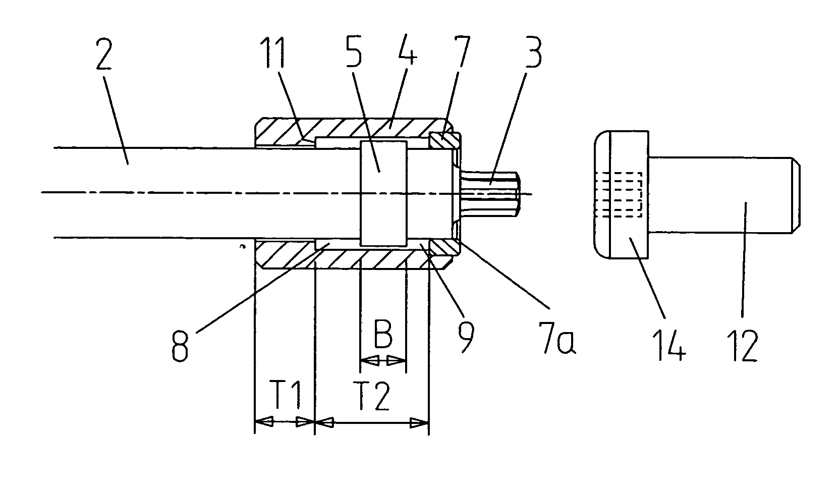
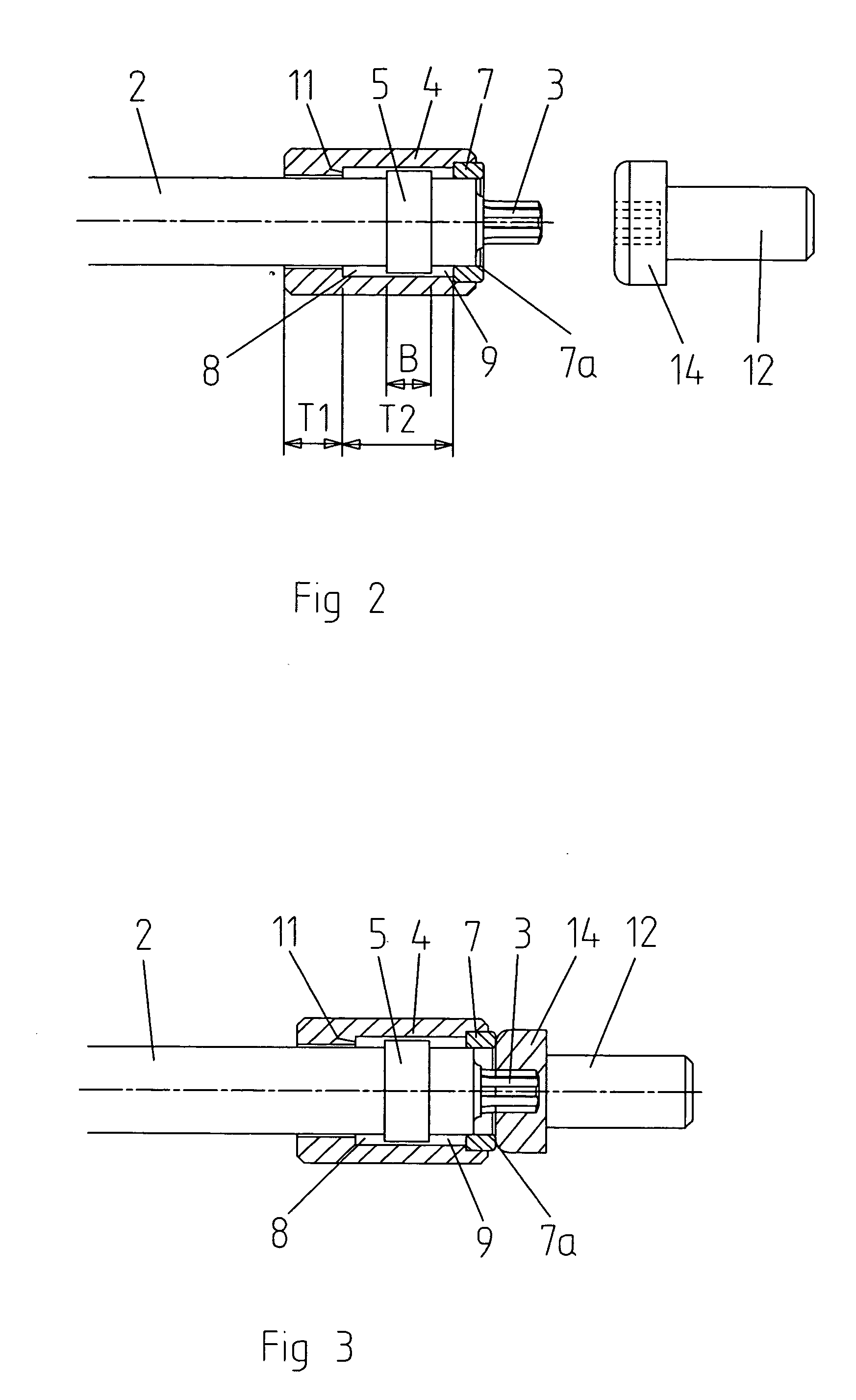
[0028]FIG. 2 shows the details of the construction of the magnetic screw holding device according to the invention. Into the tubular sleeve 4, made of non magnetic conducing material, the ring magnet 7 is fixed by press seat or by glue, for example. A boring in the sleeve has a length T2, and the stop ring has the length B. T1 is the length of a smaller boring in the sleeve in which the sleeve is guided on the shank so that the sleeve can easily move. The stop ring 5, a tubular sleeve at the illustrated example, is fixed on the shank 2 in a defined position relative to the profile tip 3 so that a clearance 8 between the stop ring 5 and the step 11 in the boring of the sleeve at one side and between the stop ring and the magnet 7 at the other side 9 allow the sleeve 4 to move on the shank 2 in both directions. The screw 12 has a head 14 with a recess 15 and a head diameter K. The clearance 8 is sized to allow the sleeve to move in a direction toward the profile tip 3 so that the fron...

third embodiment

[0033] For a magnet of the third embodiment, the volume and the distribution of the substance is adjusted by the construction and by tests to achieve that the magnet takes a stand-by position from which the automatic adjustment process starts as described.

[0034] Due to considerations of economy, it may be suitable not to find out the optimal size of the magnet by tests with each different profile tip but to select a magnet which in the stand-by position has a somewhat longer distance from the end of the profile tip and the movement in the direction toward the screw head does not start automatically if a small screw is put onto the profile tip. A light touch with a finger can move the sleeve or the magnet forward and start the automatic adjustment process. Starting the movement of the magnet from such a stand-by position there will be a strong magnetic force in the direction toward the shank pulling strongly the screw head onto the profile tip. This would not be the case if a stand-b...

second embodiment

[0037]FIG. 6 shows the invention with a sleeve-shaped magnet 16 with a relatively thin wall. The profile tip 3 penetrates into a screw head 14. The rear part of the magnet is inserted into the sleeve 17. It is of advantage if the sleeve encompasses the magnet as far as shortly before the front face—for protection of the magnet. The sleeve 17 is made of non magnetic-conductive material, preferably of plastic material or aluminum. The stop ring 5 is disposed between the magnet and the step in the boring of the sleeve. The position of the stop ring and the lengths of the clearances between the stop ring and the step in the boring at one side and the rear end of the magnet at the other side are determined in the same way as in the embodiment with ring magnet. It was found that for the sleeve-shaped magnet, a relation length to outer diameter greater than 1, at least 0.4, and a wall-thickness of 0.8 to 2.5 mm, depending from the diameter, is of advantage.

[0038] The longitudinal section F...


PUM


Abstract

A magnetic screw-holding device is assembled close to the profile tip on the shank of a hand-screwdriver or screwdriver-insert with long shank. The device essentially consists of a sleeve made of non magnetic-conducing material in which a magnet is fixed at the front side or of a magnet made of magnetic material embedded in a plastic binder produced by injection molding. The sleeve with the magnet or the magnet can easily move in longitudinal direction and is or can be brought into such a position relative to the profile tip that by the force of the magnet-field the sleeve or the magnet moves automatically into a position in which the front face of the magnet contacts the surface of the screw head and also attracts the screw onto the profile tip so that it completely penetrates into the recess in the screw head if a screw is placed on the profile tip.

Description

CLAIM OF PRIORITY [0001] This application claims priority to German patent applications 203 12 920.2, filed on Aug. 18, 2003, and 103 42 033.9, filed on Aug. 28, 2003. The contents of German patent applications 203 12 920.2 and 103 42 033.9 are incorporated in their entireties herein by this reference. FIELD OF THE INVENTION [0002] The present invention concerns a magnetic device for hand screwdrivers and screwdriver inserts with a long shank to hold screws on the profile tip of the driver. BACKGROUND OF THE INVENTION [0003] There are magnetic devices on the market or known from the patent literature which are designed to be an adapter for short screwdriver-inserts and are equipped with a permanent magnet to hold screws on the tip of the screwdriver-inserts. These kinds of magnetic screw-holding devices are described in U.S. Pat. Nos. 3,392,767, and 5,724,873 and in DE 101 48 943.9 and DE 199 07 837. EP 1 027 959 A2 describes a magnetic screw-holding device which is assembled on the...

Claims


Application Information

Patent Timeline
IPC IPC(8): B25B15/02B25B23/12
CPCB25B23/12B25B15/02
Inventor HOLLAND-LETZ, MARTIN
Owner FELO WERKZEUGFAB HOLLAND LETZ
Why Eureka
Try Eureka