Fuel injection control apparatus and fuel injection control method for internal combustion engine

a technology of fuel injection control apparatus and internal combustion engine, which is applied in the direction of electric control, liquid fuel feeder, machines/engines, etc., can solve the problems of misfire, misfire, and likely misfire in the operational range of the engine, so as to prevent misfires and prevent fuel economy from being lowered.

Inactive Publication Date: 2005-05-12
TOYOTA JIDOSHA KK
View PDF3 Cites 23 Cited by
  • Summary
  • Abstract
  • Description
  • Claims
  • Application Information

AI Technical Summary

Benefits of technology

[0009] Accordingly, it is an objective of the present invention to provide a fuel injection control apparatus and a fuel injection control method that readily prevents misfires while preventing the fuel economy from being lowered in an internal combustion engine that includes a fuel injection valve for injecting fuel into the cylinder in addition to a fuel injection valve for injecting fuel into the intake passage.

Problems solved by technology

However, if, for example, the fuel injection amount falls below a requested fuel injection amount due to deposits collected on the nozzle of the injection valve, the air-fuel ratio of the air-fuel mixture in the vicinity of the ignition plug will be leaner than the stoichiometric air-fuel ratio, which can cause a misfire to occur.
Such a misfire is likely to occur in an operational range of the engine in which the requested fuel injection amount is small, for example, when the engine is idling.
Incidentally, in an internal combustion engine having an in-cylinder injection valve, a misfire can occur even during homogeneous stoichiometric combustion in which fuel is injected during the intake stroke.
This is because when fuel is injected during the intake stroke, the injected fuel is not sufficiently diffused throughout the entire combustion chamber by the time of ignition.
As a result, due to an inhomogeneous air-fuel mixture, the air-fuel ratio in the vicinity of the ignition plug is lean, which may cause a misfire to occur.
However, performing the stratified stoichiometric combustion, in which the fuel injection amount is greater than that in the stratified lean combustion, lowers the fuel economy.

Method used


Image

  • Fuel injection control apparatus and fuel injection control method for internal combustion engine
  • Fuel injection control apparatus and fuel injection control method for internal combustion engine
  • Fuel injection control apparatus and fuel injection control method for internal combustion engine

Examples


Embodiment Construction

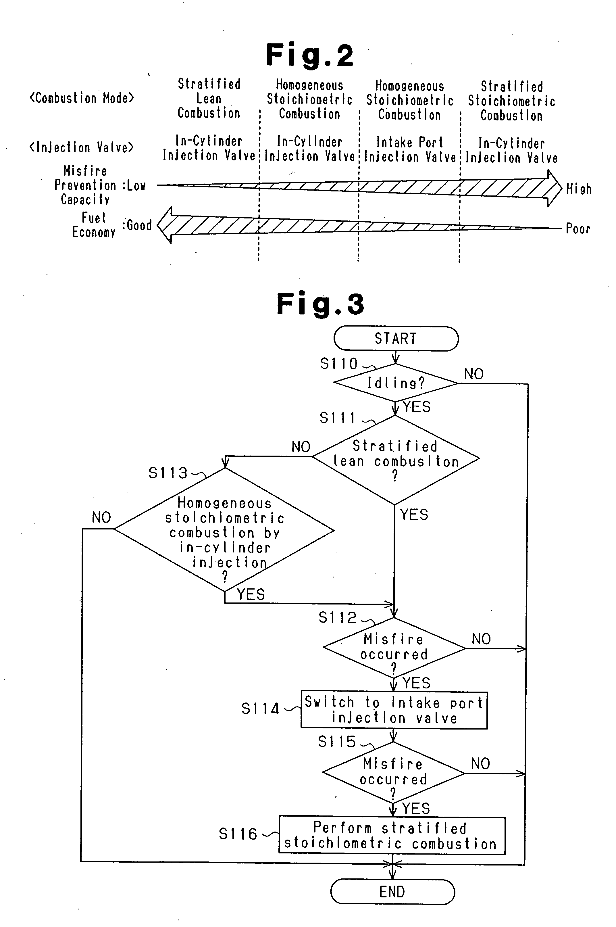
[0018] A preferred embodiment of the present invention will now be described with reference to FIGS. 1 to 3.

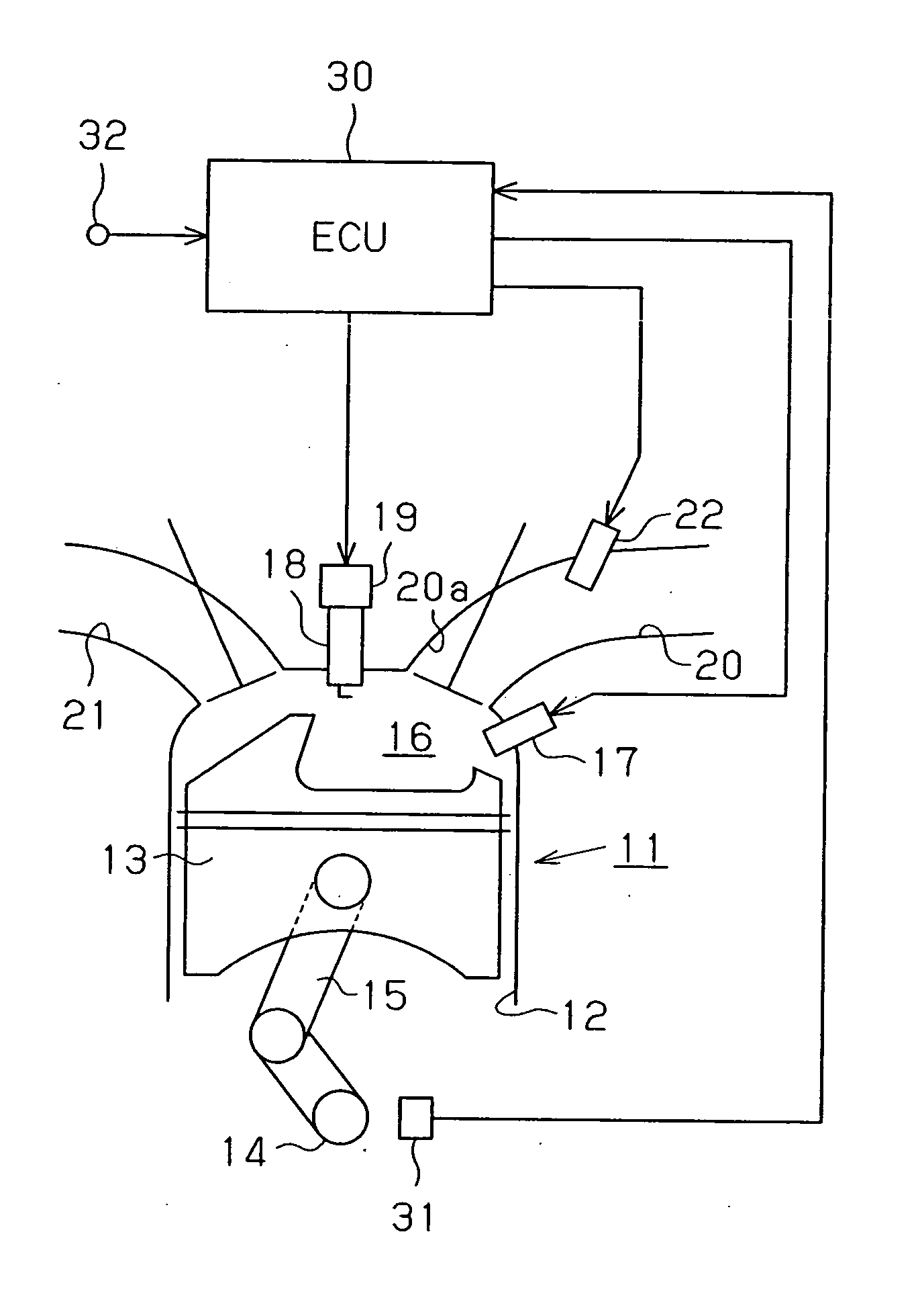
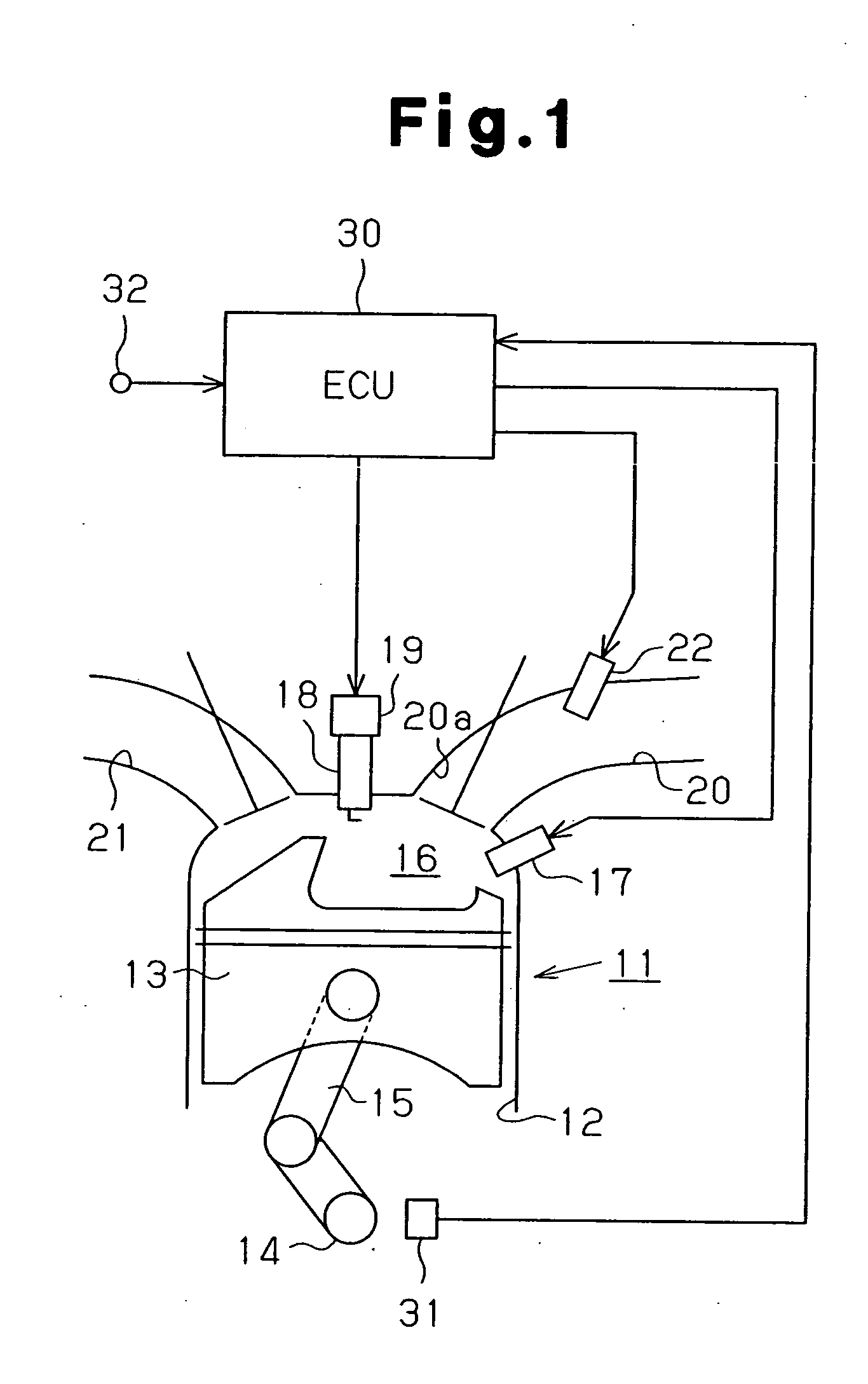
[0019] As shown in FIG. 1, a fuel injection control apparatus according to this embodiment is applied to a four-cycle cylinder injection internal combustion engine 11. The engine 11 includes a piston 13 accommodated in a cylinder 12. The piston 13 is connected via a connecting rod 15 to a crankshaft 14, which is the output shaft for the engine 11. The connecting rod 15 converts reciprocation of the piston 13 into rotation of the crankshaft 14.

[0020] A combustion chamber 16 is defined in the cylinder 12 above the piston 13. The engine 11 includes an in-cylinder injection valve 17, which functions as a first fuel injection valve for directly injecting fuel into the combustion chamber 16. The in-cylinder injection valve 17 receives highly pressurized fuel through a fuel supply mechanism (not shown). The pressure of the supplied fuel is adjusted to a predetermined value. When th...


PUM


Abstract

An internal combustion engine includes an in-cylinder injection valve and an intake port injection valve. The engine is operated in a combustion mode that is selected from at least stratified lean combustion and homogeneous combustion. An ECU selects the combustion mode according to the operational state of the engine, and controls the fuel injection valves in a fuel injection mode that corresponds to the selected combustion mode. When a misfire is detected while the engine is operated in the stratified lean combustion or the homogeneous combustion, the ECU switches the fuel injection mode such that the ratio of the amount of fuel injected from the intake port injection valve to the entire amount of fuel supplied into the cylinder is increased. As a result, misfires are suppressed while preventing the fuel economy from deteriorating.

Description

BACKGROUND OF THE INVENTION [0001] The present invention relates to an apparatus and a method for controlling fuel injection in an internal combustion engine that includes a first fuel injection valve for injecting fuel into a cylinder and a second fuel injection valve for injecting fuel into an intake passage. [0002] Conventionally, in an internal combustion engine having an in-cylinder injection valve for injecting fuel into a cylinder, “compression stroke injection” is performed to inject fuel into a combustion chamber during the compression stroke of a piston, so that stratified lean combustion, in which the air-fuel ratio is leaner than the stoichiometric air-fuel ratio, is performed. In the stratified lean combustion, a combustible air-fuel mixture having the stoichiometric or richer air-fuel ratio is generated only in the vicinity of the ignition plug. Thus, even if the overall air-fuel ratio in the combustion chamber is lean, the combustion is stabilized. As a result, the fu...

Claims


Application Information

Patent Timeline
Patent Type & Authority Applications(United States)
IPC IPC(8): F02M63/00F02D41/04F02D41/14F02D41/22F02D41/30F02D41/34F02D45/00F02M69/04
CPCF02D41/1498F02D41/3029F02M69/046F02D2200/1015F02D41/3094F02D41/04F02D41/22
Inventor OHTANI, MOTOKI
Owner TOYOTA JIDOSHA KK
Why Eureka
Try Eureka