Fuel injector for internal combustion engine

Inactive Publication Date: 2005-05-12
TOYOTA JIDOSHA KK
View PDF5 Cites 41 Cited by
  • Summary
  • Abstract
  • Description
  • Claims
  • Application Information

AI Technical Summary

Benefits of technology

[0006] It is an object of the present invention to provide a fuel injector, which includes an in-cylinder fuel injection valve an...

Problems solved by technology

In this case, the reciprocation of the plunger repetitive...

Method used


Image

  • Fuel injector for internal combustion engine
  • Fuel injector for internal combustion engine
  • Fuel injector for internal combustion engine

Examples


first embodiment

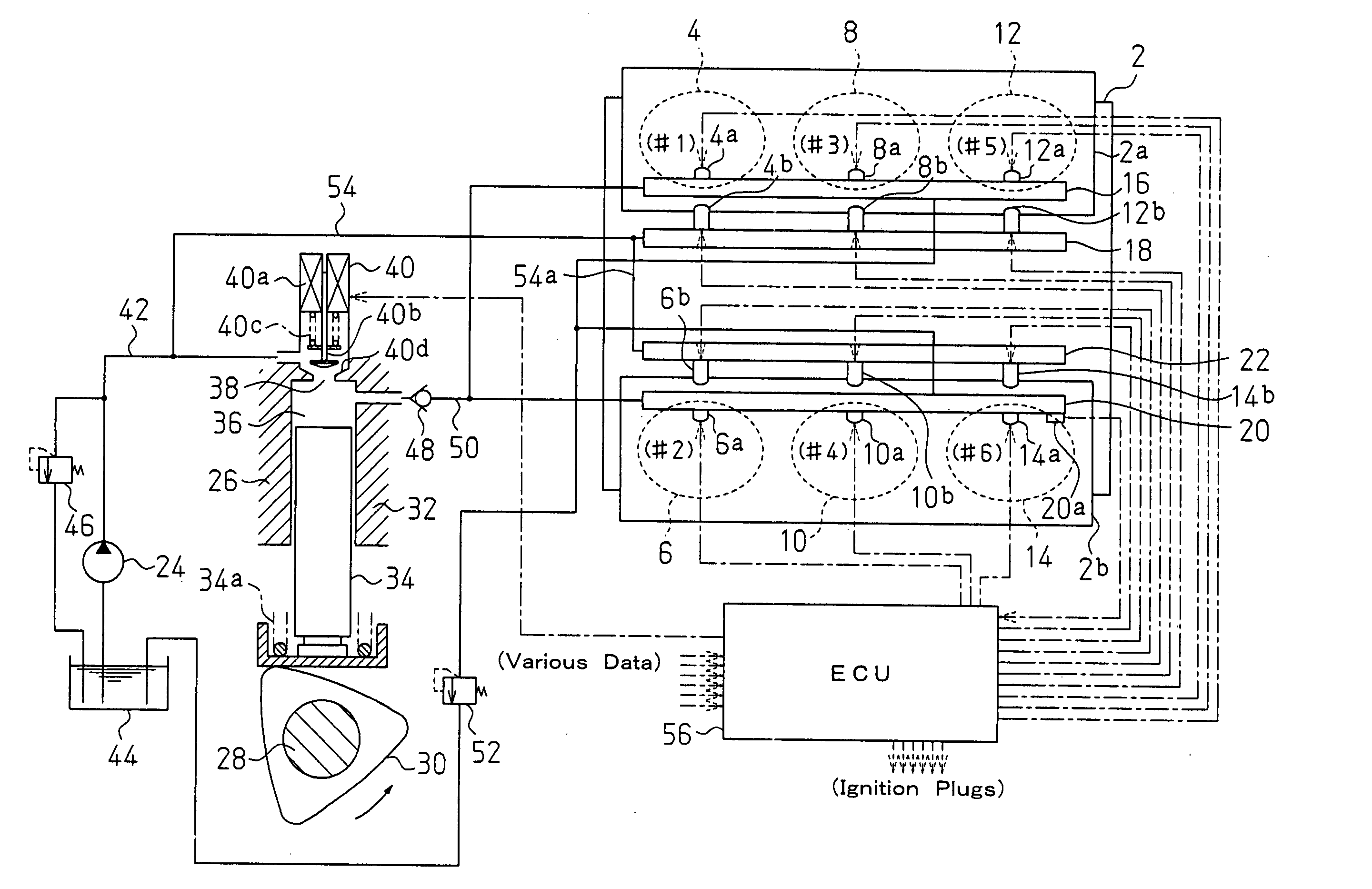
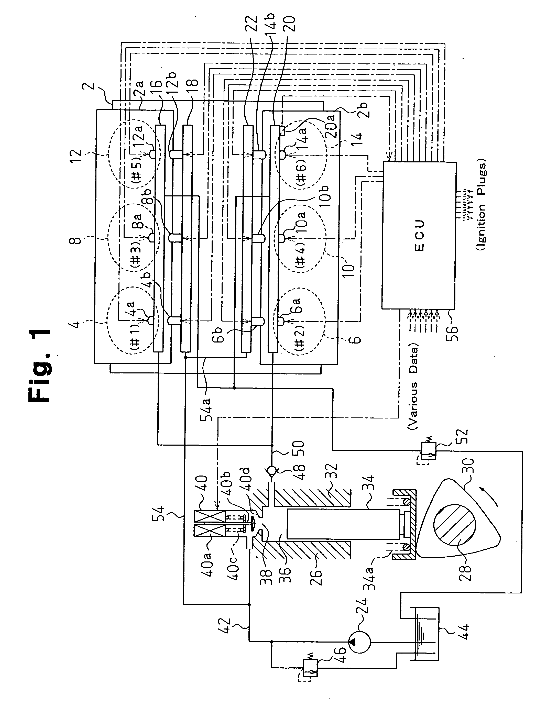
[0038]FIG. 1 is a schematic diagram of an internal combustion engine and a fuel supply system to which a fuel injector according to the present invention is applied. The internal combustion engine is a V-type six cylinder gasoline engine 2 including two banks 2a and 2b. The first bank 2a includes a first cylinder 4, a third cylinder 8, and a fifth cylinder 12. The second bank 2b includes a second cylinder 6, a fourth cylinder 10, and a sixth cylinder 14.

[0039] The cylinders 4, 8, and 12 of the first bank 2a are respectively provided with in-cylinder fuel injection valves 4a, 8a, and 12a. The in-cylinder fuel injection valves 4a, 8a, and 12a are each supplied with high pressure fuel from a high pressure fuel distribution pipe 16 to directly inject fuel into a corresponding combustion chamber. The cylinders 4, 8, and 12 are communicated with intake ports in which intake port fuel injection valves 4b, 8b, and 12b are arranged, respectively. The intake port fuel injection valves 4b, 8b,...

second embodiment

[0056] the present invention will now be discussed.

[0057] Referring to FIG. 5, this embodiment differs from the first embodiment in the high pressure pump control and an electromagnetic valve 140, which adjusts the amount of the relatively low pressure fuel drawn into the high pressure pump 26. The other parts are the same as the first embodiment. Like or same reference numerals are given to those components that are the same as the corresponding components of the first embodiment.

[0058] When an excitation coil 140a of the electromagnetic valve 140 is excited, the urging force of a spring 140c moves a valve body 140b in a direction opposite to the pressurizing chamber 36 against the urging force of the spring 140c until the valve body 140b is engaged with a seat 140d. This closes the electromagnetic valve 140. When the excitation coil 40a is de-excited, the urging force of the spring 140c moves the valve body 140b away from the seat 140d toward the pressurizing chamber 36. This ope...

third embodiment

[0067] the present invention will now be discussed.

[0068] Referring to FIG. 8, in this embodiment, an electromagnetic shutting valve 42b is arranged in a low pressure fuel intake passage 42a, which is connected to the low pressure fuel path 42 and the high pressure pump 26. Further, instead of the high pressure pump control of FIG. 2, the high pressure pump control illustrated in FIG. 9 is executed. The other parts are the same as the second embodiment. Like or same reference numerals are given to those components that are the same as the corresponding components of the second embodiment.

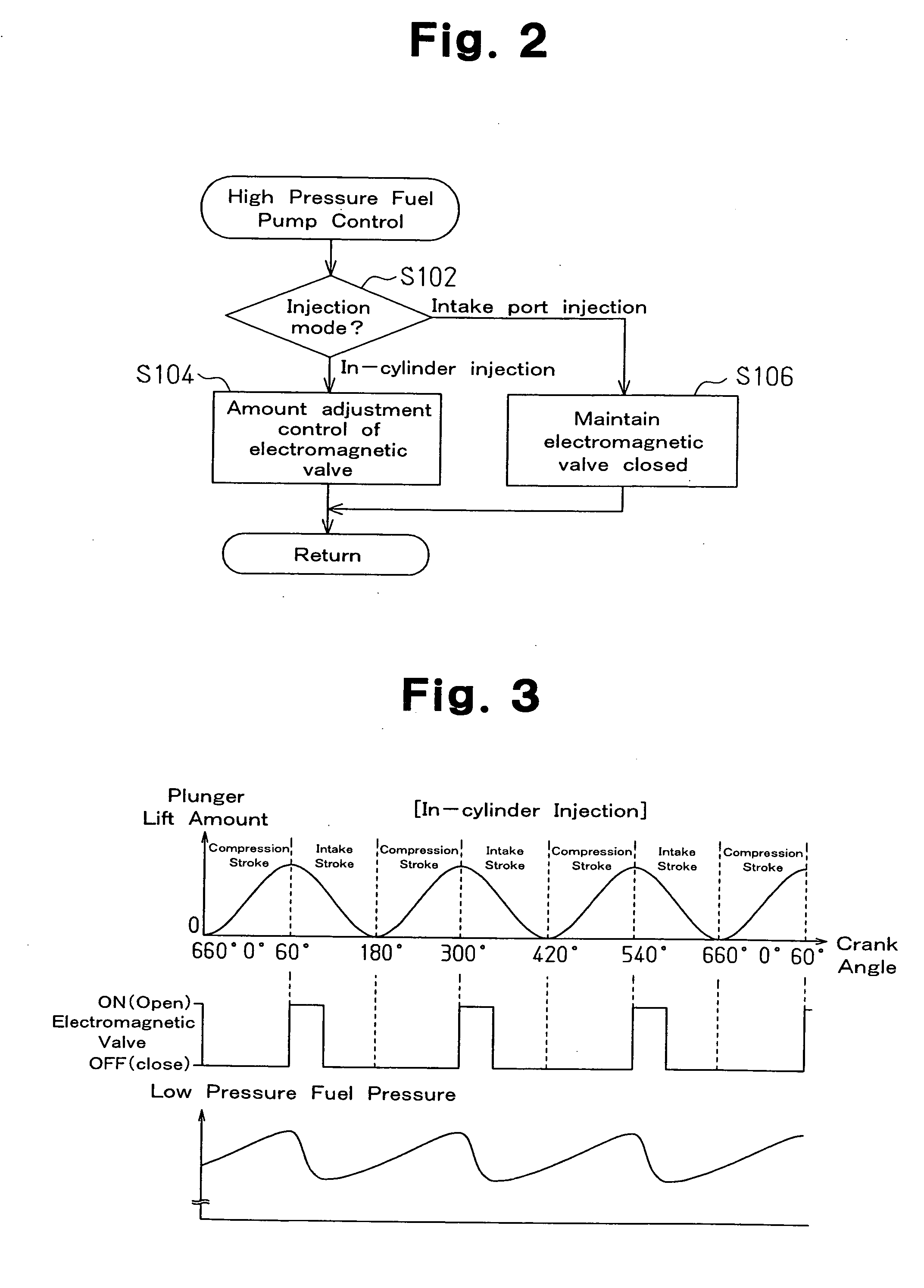
[0069] The high pressure pump control (FIG. 9) will now be described. The control of FIG. 9 is repetitively executed in predetermined cycles. When the control is started, the present injection mode is first checked (S202).

[0070] If the injection mode is “in-cylinder injection,” the electromagnetic shutting valve is de-excited and opened (S204). Thus, the low pressure fuel intake passage 42a is not...


PUM


Abstract

A fuel injector for an internal combustion engine including an in-cylinder fuel injection valve and an intake port fuel injection valve. An ECU controls an electromagnetic valve to keep a fuel inlet of a high pressure pump closed during an intake port injection mode during which fuel is injected only from an intake port fuel injection valve. As a result, even if the plunger reciprocates in the high pressure pump, fuel does not flow between the high pressure pump and a low pressure fuel path. Thus, pressure pulsation that would be caused by the operation of the high pressure pump does not occur in low pressure fuel.

Description

CROSS-REFERENCE TO RELATED APPLICATIONS [0001] This application is based upon and claims the benefit of priority from prior Japanese Patent Application No. 2003-381535, filed on Nov. 11, 2003, the entire contents of which are incorporated herein by reference. BACKGROUND OF THE INVENTION [0002] The present invention relates to a fuel injector for an internal combustion engine that is provided with an in-cylinder fuel injection valve and an intake port fuel injection valve. [0003] A fuel injector including an in-cylinder fuel injection valve, which directly injects fuel into a combustion chamber, and an intake port fuel injection valve, which injects fuel into an intake port, is known in the prior art. The fuel injector is switched between an in-cylinder injection mode and an intake port injection mode in accordance with driving conditions (refer to Japanese Laid-Open Patent Publication No. 7-103048). [0004] The in-cylinder fuel injection valve injects high pressure fuel supplied from...

Claims


Application Information

Patent Timeline
IPC IPC(8): F02M37/00F02B75/12F02D41/02F02D41/34F02D41/38F02M39/02F02M55/00F02M55/02F02M59/10F02M59/30F02M59/34F02M59/36F02M59/44F02M63/00F02M63/02F02M69/04F02M69/46
CPCF02B2075/125Y02T10/123F02D41/3836F02D41/3854F02D2041/3881F02M39/02F02M59/102F02M59/30F02M59/366F02M59/44F02M63/02F02M63/021F02M63/0225F02M63/025F02M63/0285F02M69/462F02M69/465F02D41/3094Y02T10/12
Inventor YAMAZAKI, DAICHIKURATA, NAOKISAKAI, MITSUTOAKITA, TATSUHIKO
Owner TOYOTA JIDOSHA KK
Why Eureka
Try Eureka