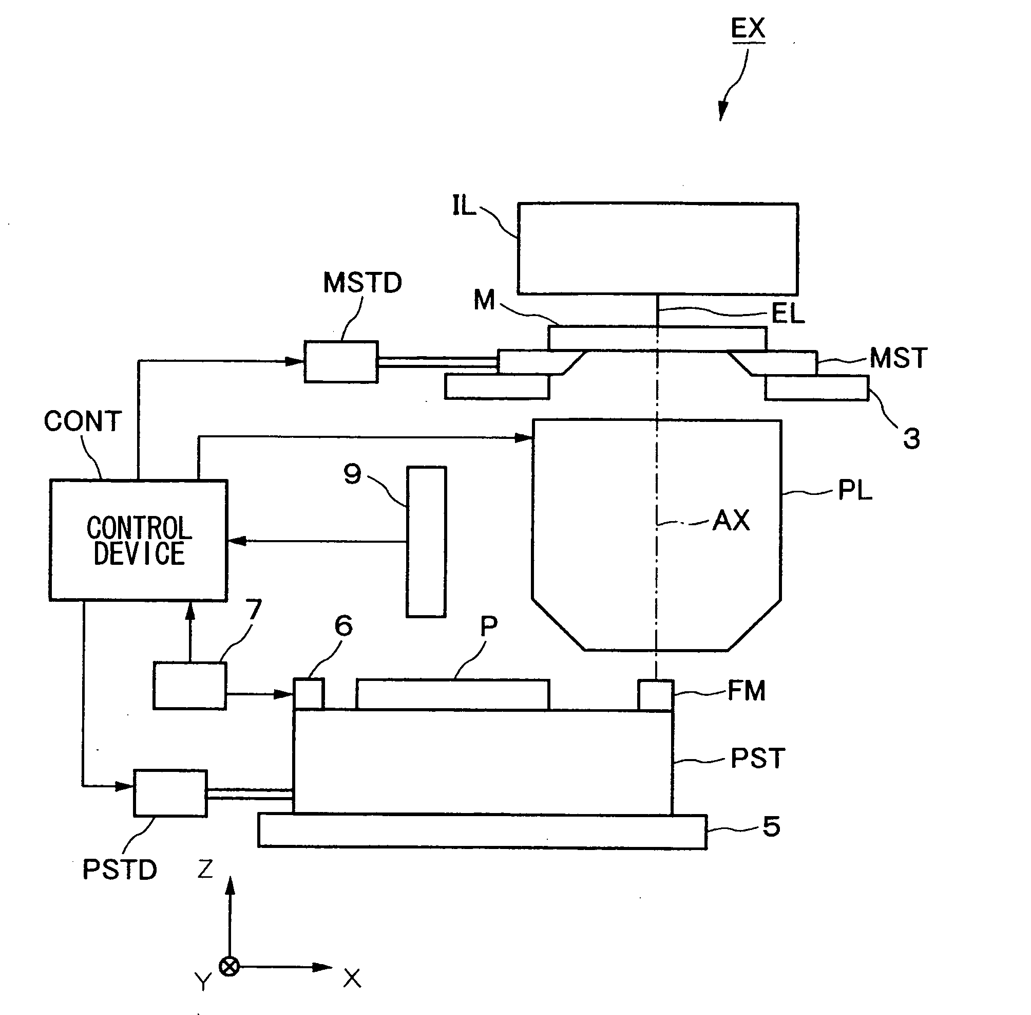
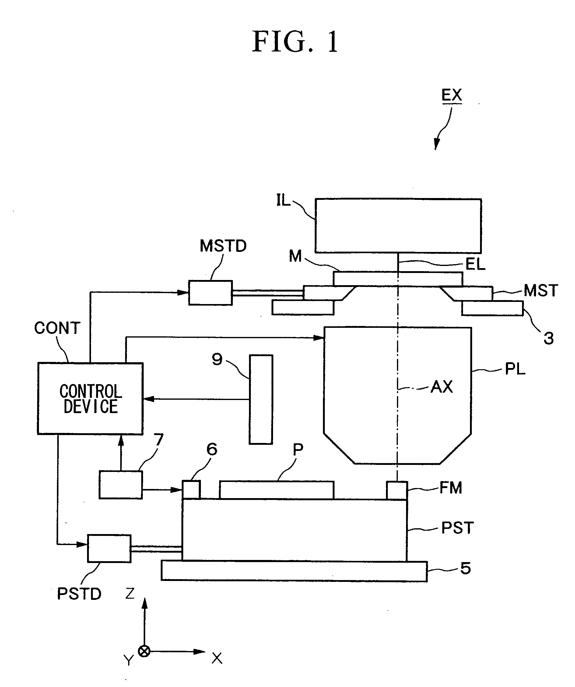
Mark for position detection, mark identification method, position detection method, exposure method, and positional information detection method

a technology for position detection and mark identification, applied in the direction of instruments, photomechanical treatment, measurement devices, etc., can solve the problems of reducing the size of the transcription region upon the substrate, deteriorating the accuracy of alignment, and difficult to specify the alignment mark for aligning the pattern from the subsequent layer, etc., to enhance the simplicity of the detection process, increase the quantity of information, and improve the accuracy

Inactive Publication Date: 2005-05-12
NIKON CORP
View PDF5 Cites 27 Cited by
  • Summary
  • Abstract
  • Description
  • Claims
  • Application Information

AI Technical Summary

Benefits of technology

[0019] According to the present invention, by providing the second pattern which is associated in a predetermined positional relationship with respect to the first pattern for outputting positional information, by detecting the state of this second pattern, even if a mark of the same type is present in the vicinity of the mark which is to become the subject of detection, it is possible to specify the mark for use for position detection from this plurality of marks. Furthermore, since the second pattern is made up as a combination of n patterns of N types, even without setting the region for arrangement of the marks upon the substrate to be wide, it is possible to display information of the large number of Nn types. The result of this is that, even though a large number of the same type of mark are present, it is possible to perform mark identification without squeezing down the pattern transcription region upon the substrate.
[0056] Furthermore, according to the present invention, by providing non subject marks at equal spacing around the vicinity of the subject mark, it is possible to avoid the inconvenience that the surface of the device may contact at an inclination with respect to the polishing surface of a CMP device, so that it is possible to perform a polishing procedure with good accuracy. Accordingly, it is possible to manufacture a device which is endowed with the desired functionality.

Problems solved by technology

In this case since, with a prior art alignment optical system, during the fine alignment, it is not decided whether any mark is the subject for detection, or whether a mark within the measurement region is the subject of detection, accordingly it may happen (undesirably) that the measurement of the position of an alignment shot region is performed based upon an erroneous alignment mark which is not the subject of detection, which will remarkably deteriorate the accuracy of alignment.
In this case as well, it becomes difficult to specify the alignment mark for aligning the pattern from the subsequent layer from the large number of alignment marks which include the alignment marks for the previous layer (or the previous to the previous layer).
However, the pattern transcription region upon the substrate is reduced in size by just the area of the forbidden zone, and the presence of a forbidden zone is not desirable from the point of view of efficient utilization of the substrate, because it imposes a restriction upon the ease of arrangement of the circuitry, and the like.
However, since the number of search marks upon the substrate which are utilized in the search alignment procedure is 2 or 3, accordingly a large number of unused search marks which are not used in the search alignment procedure come to be formed upon the substrate.
Since the mere existence of these search marks reduces the size of the pattern transcription region upon the substrate, this is not desirable from the point of view of efficient utilization of the substrate.
Even further, in the search alignment procedure, although two or more search marks which are separated upon the substrate are detected by the alignment optical system, when, after the alignment optical system detects the first search mark, it goes to detect the second search mark within the measurement region of the alignment optical system, if for example the substrate is deformed, since the actual relative position of the first search mark and the second search mark is different from the design relative position, the procedure of arranging the second search mark within the measurement region of the alignment optical system does not proceed smoothly.
However, when compression processing is performed, if the mark is small, it may happen that it becomes impossible to perform detection of the position of the mark because the mark image is, undesirably, spoilt.
Still furthermore, when manufacturing a micro device, although a CMP (Chemical Mechanical Polishing) procedure may be performed in order to flatten the surface of the device, it sometimes happens that, due to the concave and convex state of the surface of the device, the surface of the device contacts the polishing surface of the CMP device at a certain inclination, which is undesirable, so that it may happen that the state of the polishing becomes uneven.

Method used


Image

  • Mark for position detection, mark identification method, position detection method, exposure method, and positional information detection method
  • Mark for position detection, mark identification method, position detection method, exposure method, and positional information detection method
  • Mark for position detection, mark identification method, position detection method, exposure method, and positional information detection method

Examples


second embodiment

[0195] Next, the second embodiments of the mark for position detection and the mark identification method of the present invention will be explained with reference to FIGS. 11A through 11I. Here, in the following explanation, to structural elements which are the same as ones in the first embodiment described above or which are equivalent thereto, the same reference symbols will be affixed, and their explanation will be curtailed.

[0196] In FIGS. 11A through 11I, the identification mark 2 is made as an assembly of bit marks 30. Although in this embodiment the bit marks 30 are “□”, it would also be acceptable for them to be “◯” or “Δ”. Just as in the first embodiment, each of these bit marks 30 is formed in a respective region R1 through R4 which is set in a predetermined positional relationship with respect to the alignment mark 1. It should be understood that the number of regions of the identification mark 2 is not limited to four; it would be acceptable for it to be any natural nu...

third embodiment

[0202] Next, the third embodiment of the present invention will be explained with reference to FIGS. 12 and 13A through 13E.

[0203] In FIG. 12, each of the four regions R1 through R4 of the identification mark 2 is arranged so that they almost do not mutually overlap in the X axis direction and in the Y axis direction. And, by arranging the bit marks 30 which were explained in the second embodiment in each of these regions R1 through R4, it is possible to enhance the detection accuracy of the bit marks 30 by the alignment optical system 9, and thus to enhance the identification accuracy of the identification mark 2.

[0204] In other words although, as described above, the bit marks 30 are detected by scanning the photographic element for the X axis and the photographic element for the Y axis, if, for example, as shown in FIG. 13A, the region R1 and the region R2 are set along the X axis direction, and the bit marks 30 are individually provided in each of the region R1 and the region ...

fourth embodiment

[0206] Next, the fourth embodiment of the present invention will be explained with reference to FIG. 14.

[0207] As shown in FIGS. 14A through 14C, the identification marks 2 are arranged to extend along the prolongation of the direction of extension of the pattern portions of the alignment mark 1. In the example shown in FIG. 14A, the identification mark 2 is provided in a position which continues to the +Y side of the pattern portions 12L which extend in the Y axis direction among the alignment marks 1, and is provided on the +Y side of the central pattern portion 12L among the three pattern portions 12L which are provided in the illustrated mark 11 for Y detection upon the left side, and on the +Y side of the central pattern portion 12L among the three pattern portions 12L which are provided in the illustrated mark 11 for Y detection upon the right side. In the example shown in FIG. 14B, the identification marks 2 are provided on the +Y side of the central pattern portion 12L amon...


PUM

PropertyMeasurementUnit
wavelengthaaaaaaaaaa
lengthaaaaaaaaaa
distanceaaaaaaaaaa

Abstract

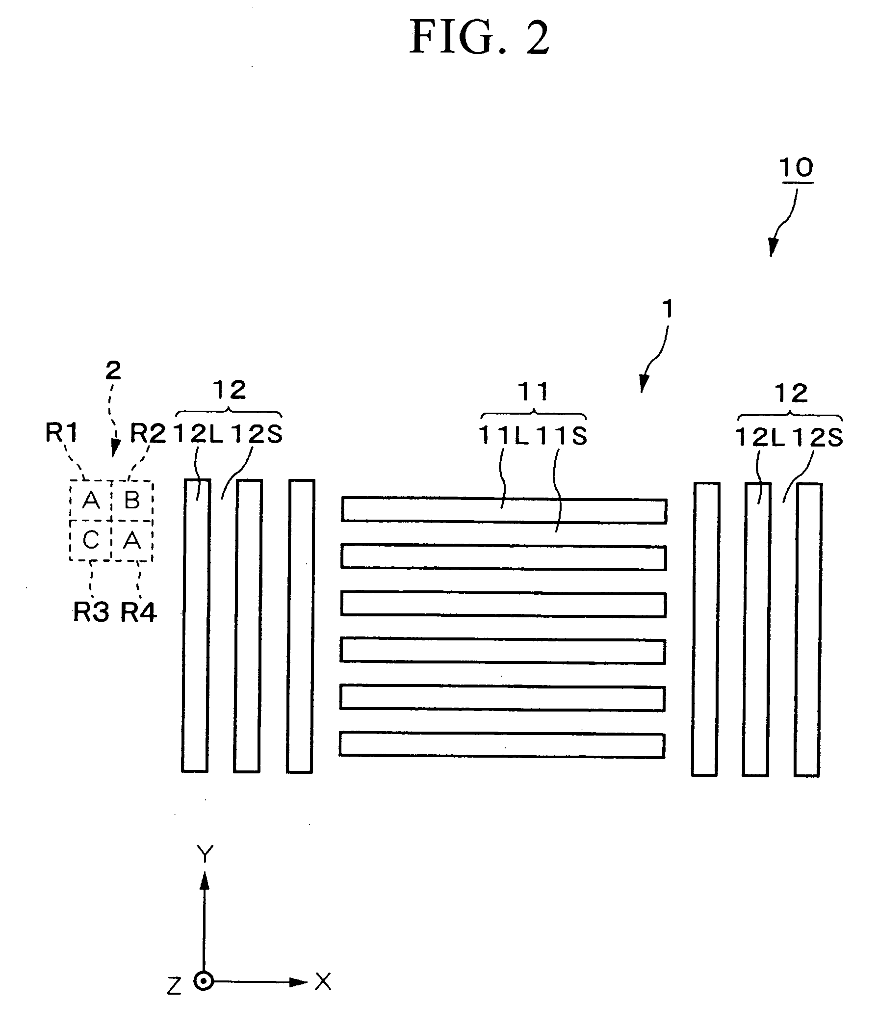
The present invention proposes a mark for position detection which can reliably detect a mark which is the subject of detection, even when a large number of marks of the same type are present in the vicinity of this mark which is to be the subject of detection. A mark for position detection 10, which is provided upon a photosensitive substrate P, and which is used when detecting positional information for the photosensitive substrate P by an alignment optical system 9, comprises an alignment mark 1 for outputting positional information to a control device CONT by being observed by the alignment optical system 9, and a identification mark 2 which is arranged in a predetermined positional relationship with the alignment mark 1, consists of a combination of four patterns of three types, and expresses 34 types of information.

Description

TECHNICAL FIELD BACKGROUND OF THE INVENTION [0001] 1. Field of the Invention [0002] The present invention relates: to a mark for position detection, which is provided upon an object, and which is used when detecting positional information of this object; to a mark identification method and a mark detection method for identifying a specific mark from a plurality of marks; to an exposure method, in which a pattern upon a substrate is exposed to light; and to a positional information detection method. [0003] 2. Description of Related Art [0004] A micro device such as a semiconductor element or a liquid crystal display element or the like is manufactured by repeating each of a film manufacture processing process, a processing for exposure to light process, and an etching processing process and the like a plurality of times, thus layering a plurality of patterns upon a substrate. In this processing for exposure to light, an exposure device is utilized for transcribing a pattern which is ...

Claims


Application Information

Patent Timeline
Patent Type & Authority Applications(United States)
IPC IPC(8): G03F9/00
CPCG03F9/7076G03F9/7046
Inventor KOKUMAI, YUUJI
Owner NIKON CORP
Why Eureka
Try Eureka