Display device, image display device and display method

a technology of image display and display method, which is applied in the direction of identification means, instruments, optics, etc., can solve the problems of low light utilization efficiency of illumination light source, and high power consumption of such devices, and achieve simple structure, high light utilization efficiency, and contrast

Inactive Publication Date: 2005-05-12
FUJIFILM CORP +1
View PDF5 Cites 6 Cited by
  • Summary
  • Abstract
  • Description
  • Claims
  • Application Information

AI Technical Summary

Benefits of technology

[0007] The present invention has been made in order to solve the above-described problems. It is an object of the present invention to provide a display device which has high light utilization efficiency, contrast, and response speed, is capable o

Problems solved by technology

While a liquid crystal display device using TFTs has advantages in that response speed thereof is fast and it can display a clear multicolor moving picture, the liquid crystal display device has disadvantages in that power consumption thereof is high, electric power is required for maintaining an image, a viewing angle thereof is narrow, and so on, because the liquid crystal display device requires an illumination light source such as a backlight and light utilization efficiency of the illumination light source is also low.
Accordingly, each of the image display devices has problems in that the light utilization efficiency is in principle poor and in that contrast of the device is low.
However, the device involves a problem in that it is difficult to let a desired color come out after rewriting because it is difficult to separate the image into the three colors when the image display is turned off.
Further

Method used


Image

  • Display device, image display device and display method
  • Display device, image display device and display method
  • Display device, image display device and display method

Examples


first embodiment

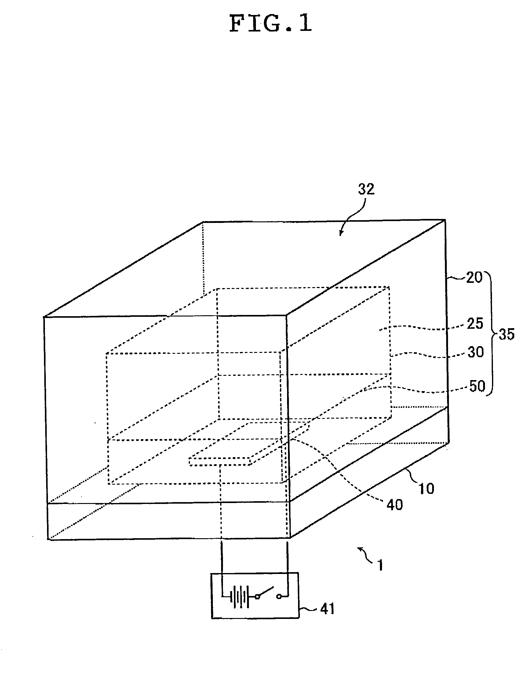
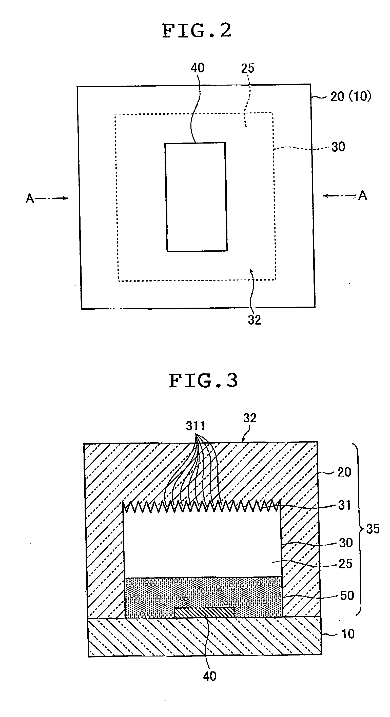
[0031] A display device of the present invention will be described below. FIG. 1 is a perspective view showing a display device 1 as an embodiment of the display device of the present invention. FIG. 2 is a plan view of the display device 1, and FIG. 3 is a longitudinal sectional view showing a cut surface obtained by cutting the display device 1 along a plane which passes through a line A-A in FIG. 2 and is perpendicular to a sheet surface. As shown in FIGS. 1 to 3, in the display device 1 according to this embodiment, a light transmitting substrate 20 as a transparent member is stacked on a support substrate 10.

[0032] A material of the support substrate 10 is not particularly limited as long as it is provided with visible light transmission characteristics and resistance to a liquid 50 to be described later (hereinafter, referred to as “liquid resistance”). Examples of such a material include glass and acrylic resin. A thickness of the support substrate 10 is not particularly lim...

second embodiment

[0066] Next, a second embodiment of the present invention will be described. In this embodiment, a display unit provided with a multilayer structure in which the plural display devices are stacked will be described. FIG. 6 is a longitudinal sectional view showing a state where the display unit according to this embodiment is cut along a vertical plane. The display unit according to this embodiment is provided with a multilayer structure in which a plurality of units are stacked, the units each being a display device similar to the display device 1 described in the above-described first embodiment. In this display unit, regularities of fine asperities which structural color forming surfaces in the respective layers have are different from one another. Specifically, as shown in FIG. 6, a display unit 90 according to this embodiment is provided with a multilayer structure in which three display devices 60, 70, and 80 are stacked in a vertical direction in FIG. 6. Each of the display de...

third embodiment

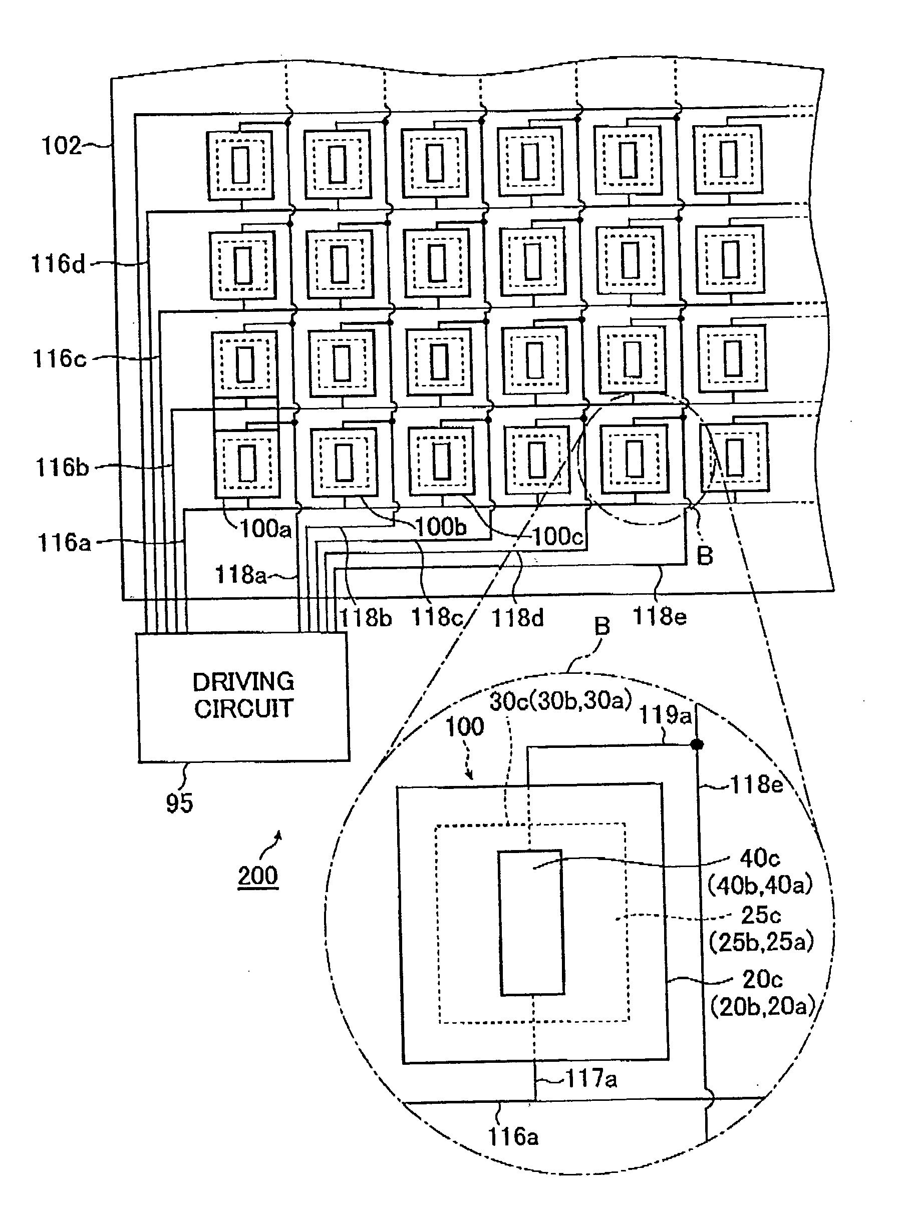
[0081] Next, an image display device according to a third embodiment of the present invention will be described. In this embodiment, an image display device with a structure in which the plural display units according to the above-described second embodiment are arranged in matrix will be described. FIG. 7 is a view showing a schematic configuration of the image display device according to this embodiment. As shown in FIG. 7, in the image display device 200 according to this embodiment, the plural display units are regularly arrayed in matrix on a board 102. The respective display units are display units 100a, 100b, 100c . . . which are the same as the display unit 90 of the above-described second embodiment. FIG. 7 is an enlarged plan view showing in a small circle 5, one of the display units arrayed on the image display device 200.

[0082] As shown in the small circle B of FIG. 7, the plural display units 100a, 100b, 100c, . . . are arranged on an upper surface of the image display...


PUM


Abstract

The display device includes a display portion having a cavity portion surrounded by wall surfaces, at least one part of the wall surfaces being formed of a transparent member and forming a structural color forming surface provided with fine asperities having predetermined regularity, a liquid being hermetically sealed to have a liquid surface in the cavity portion and having a refractive index approximately equivalent to that of the transparent member, an actuator giving a disturbance to the liquid to bring the liquid into contact with the forming surface and a control unit controlling driving of the actuator to switch reflection and transmission characteristics of light when the light is incident into the forming surface, thereby controlling color display using reflected light formed by the forming surface.

Description

BACKGROUND OF THE INVENTION [0001] The present invention relates to a display device, an image display device and an image display method, and more particularly to a display device, an image display device and a display method used for a thin image display device such as a flat panel display. [0002] Heretofore, a liquid crystal display (LCD) device has been widely used as an image display device of an information terminal apparatus such as a personal computer or a portable information terminal (personal digital assistance: PDA) or of a car navigation system. While a liquid crystal display device using TFTs has advantages in that response speed thereof is fast and it can display a clear multicolor moving picture, the liquid crystal display device has disadvantages in that power consumption thereof is high, electric power is required for maintaining an image, a viewing angle thereof is narrow, and so on, because the liquid crystal display device requires an illumination light source s...

Claims


Application Information

Patent Timeline
IPC IPC(8): G02B26/08G02B26/02G02F1/19G09F9/37G09G3/20
CPCG02B26/004G02F2203/34G02F1/19
Inventor KODAMA, KENICHIINOUE, SEIICHIYAMAMOTO, RYOICHISANADA, KAZUOKIMURA, KOICHIYOKOUCHI, TSUTOMU
Owner FUJIFILM CORP
Why Eureka
Try Eureka