High voltage generator having separate voltage supply circuit

a generator and high voltage technology, applied in the field of semiconductor devices, can solve the problems of reducing the external supply voltage applied to semiconductor memory devices within the host system, difficult to generate the required high voltage with semiconductor memory devices using conventional high voltage generators, and the relative pumping efficiency of high voltage generators also becoming a problem. achieve the effect of high voltage and efficiently generating a high voltage outpu

Inactive Publication Date: 2005-05-12
SAMSUNG ELECTRONICS CO LTD
View PDF1 Cites 10 Cited by
  • Summary
  • Abstract
  • Description
  • Claims
  • Application Information

AI Technical Summary

Benefits of technology

[0009] The present invention provides a high voltage generation circuit which efficiently generates a high voltage output for subsequent used within a semiconductor memory device.

Problems solved by technology

As a result, the externally provided power source voltages applied to semiconductor memory devices within the host systems has also been decreasing.
Accordingly, it is increasingly difficult to generate the required high voltages with semiconductor memory devices using conventional high voltage generators.
In addition to the problem of unmet overall demand for high voltages, the relative pumping efficiency of high voltage generators is also becoming a problem.
That is, as externally supplied voltages have decreases, the pumping efficiency of conventional circuits generating high voltages has markedly dropped.
Further problems arise from the decrease in externally supplied voltages.
Unfortunately, the time required to fully pre-charge the capacitors in each of these boosting stages increases proportionally, and as a result, the time for one operation increases to the point where the entire boosting timing becomes unacceptably long.

Method used


Image

  • High voltage generator having separate voltage supply circuit
  • High voltage generator having separate voltage supply circuit
  • High voltage generator having separate voltage supply circuit

Examples


Embodiment Construction

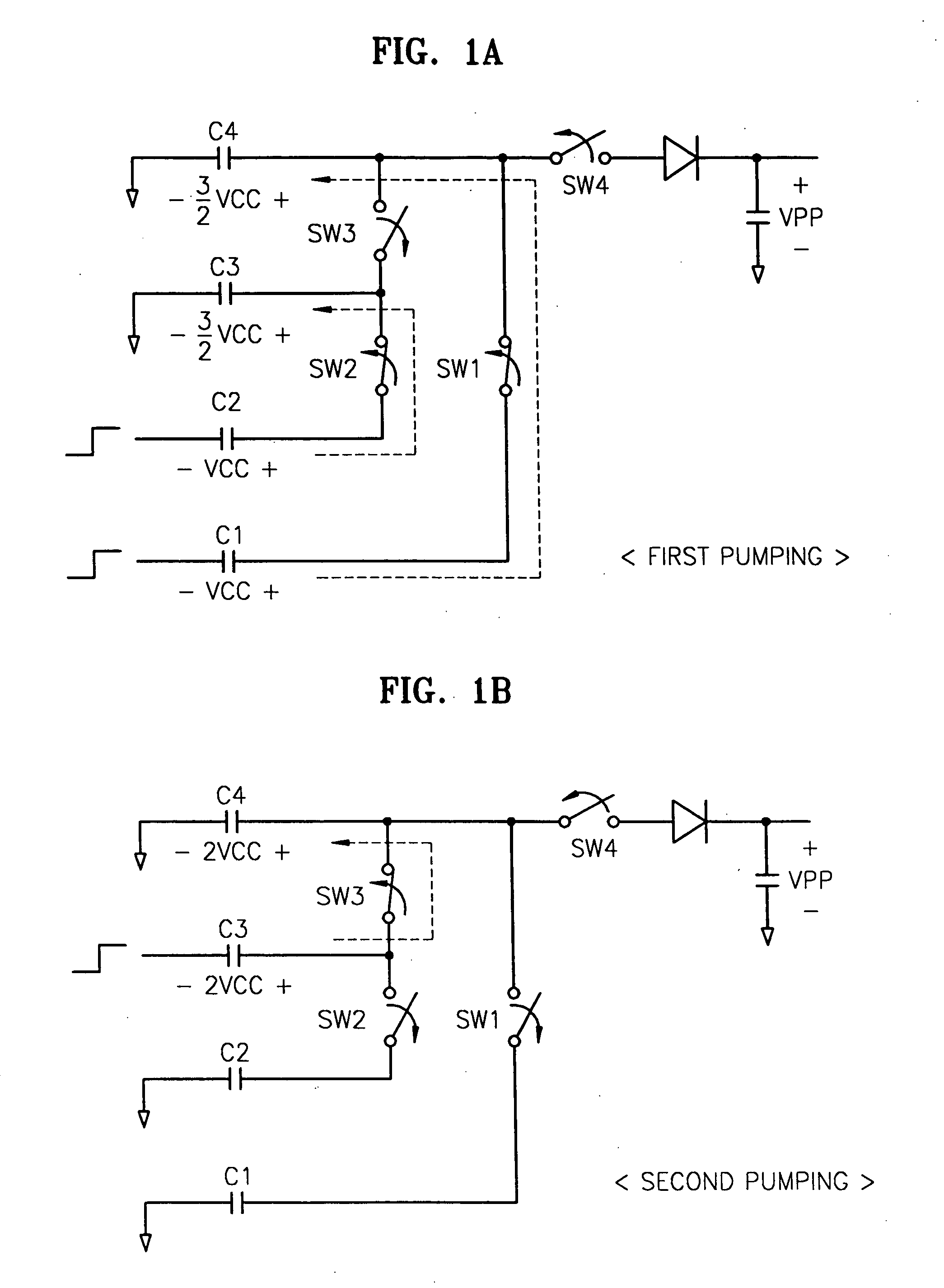
[0024] Referring to FIG. 1a, four capacitors (C1 through C4) are pre-charged from an external power source voltage (VCC). Then, a first switch (SW1) and a second switch (SW2) are turned on, and by driving C1 and C2 with the power source voltage (VCC), a first pumping operation is performed. As a result, the electrical charge from C1 is provided to C4 and the charge from C2 is provided to C3. Accordingly, a voltage level is developed on C3 and C4 that is equal to VCC+0.5 VCC.

[0025] Referring now to FIG. 1b, first switch (SW1) and second switch (SW2) are turned off, and a third switch (SW3) is turned on. Thereafter, by driving C3 with the power source voltage (VCC), a second pumping operation is performed. As a result of this second pumping operation, C3 develops a voltage level equal to VCC+1.5 VCC, and thereafter the charge stored on C3 is provided to C4, such that a voltage equilibrium is maintained. Accordingly, a voltage of 2 VCC is developed on C3 and C4.

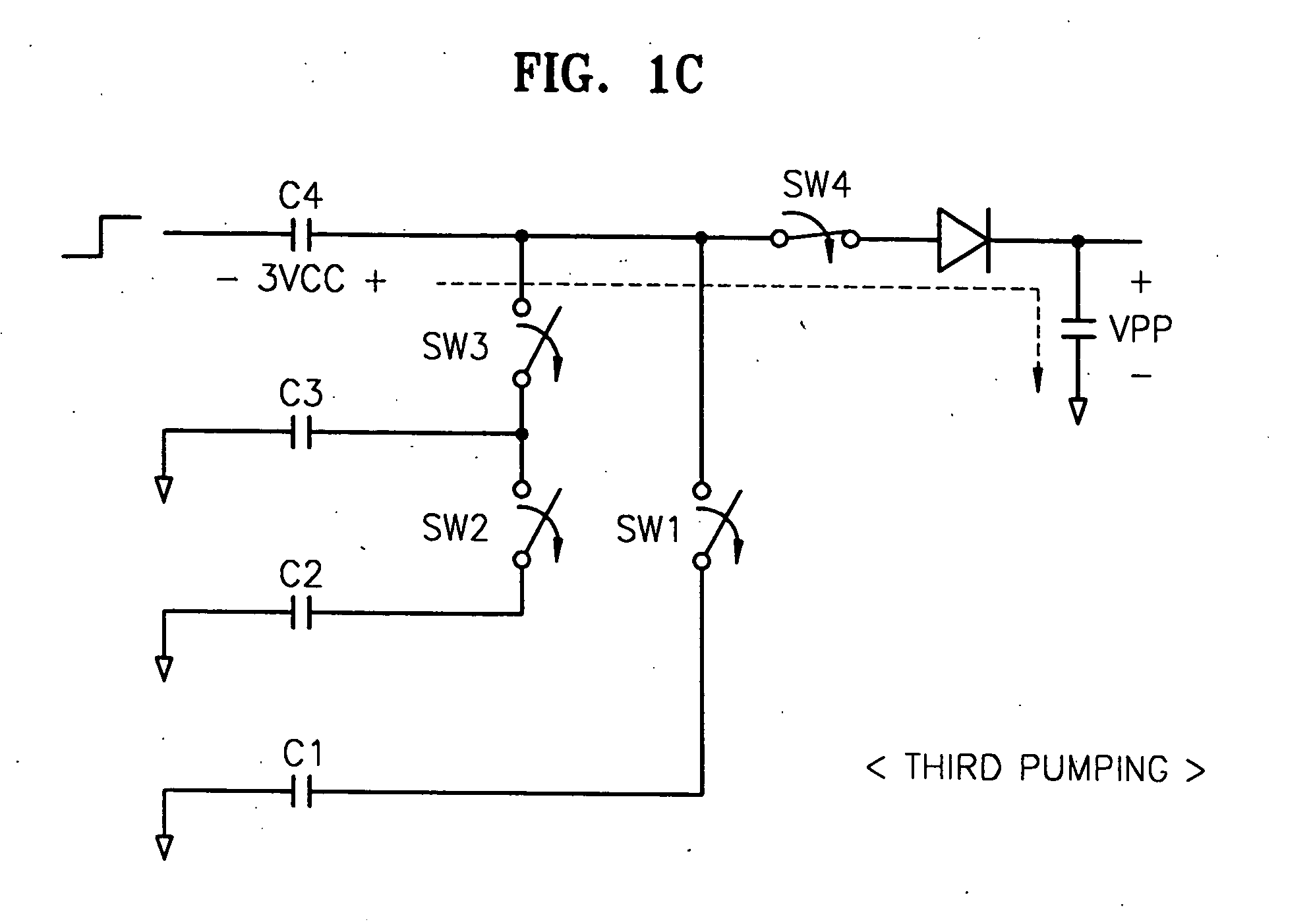
[0026] Referring now t...


PUM


Abstract

A high voltage generation circuit comprises a first boosting unit, a second boosting unit, a delay circuit which delays the output of the first boosting unit as applied the second boosting unit, a pre-charge unit, and switch units which connect respective nodes in response to control signals. A voltage supply circuit is also provided that converts an externally supplied power source voltage (VCC) to a predetermined pre-charge voltage (VPP2).

Description

BACKGROUND OF THE INVENTION [0001] 1. Field of the Invention [0002] The present invention relates generally to a semiconductor device, and more particularly, to a semiconductor device having a high voltage generator with a short pumping operation time and improved efficiency in current usage. A claim of priority is made to Korean Patent Application No. 03-78641 filed on Nov. 7, 2003 in the Korean Intellectual Property Office, the disclosure of which is hereby incorporated by reference in its entirety. [0003] 2. Description of the Related Art [0004] It is quite common for a semiconductor device to use a relatively higher voltage to drive some circuits as compared with other circuits internal to the device. For example, a semiconductor memory device will often use a voltage to drive word lines that is higher than a normally provided external voltage. The term “external” generally refers to a voltage provided by a circuit outside the semiconductor device itself, as compared with “inter...

Claims


Application Information

Patent Timeline
Patent Type & Authority Applications(United States)
IPC IPC(8): G11C5/14H02M3/07
CPCH02M3/07G11C5/145G11C5/14
Inventor JUNG, WON-CHANG
Owner SAMSUNG ELECTRONICS CO LTD
Why Eureka
Try Eureka