Signal reception device and method of signal reception timing detection

a signal reception and timing detection technology, applied in the field of signal reception devices and methods, can solve the problems of signal performance degradation, transmission performance degrade, and conventional mobile communications, and achieve the effect of improving signal transmission performance and reducing inter-symbol interferen

Inactive Publication Date: 2005-05-12
NTT DOCOMO INC
View PDF19 Cites 24 Cited by
  • Summary
  • Abstract
  • Description
  • Claims
  • Application Information

AI Technical Summary

Benefits of technology

[0035] According to the present invention, in the OFCDM transmission scheme or a multi-carrier transmission scheme, it is possible to detect an appropriate symbol synchronization timing according to a condition of a propagation path even when the multi-path interference exists, and to reduce the inter-symbol interference accompanying a timing deviation. Consequently, it is possible to improve the signal transmission performance.

Problems solved by technology

For example, a multi-carrier CDMA (Code Division Multiple Access) scheme, which involves multiplication of spread codes in a frequency axis, has tolerance for frequency-selectivity of propagation paths arising from existence of multiple paths, which causes a problem in conventional mobile communications.
The multi-path interference causes degradation of signal performance, and is a problem in the mobile communication environment.
However, as shown in FIG. 25B, when the detected symbol synchronization timing deviates from the ideal position because of influence of the propagation paths, the inter-symbol interference occurs in the FFT window section, components of adjacent OFCDM signals are extracted simultaneously, and transmission performance degrades because of the inter-symbol interference.
However, when applying the OFCDM transmission scheme to a mobile communication environment, because of the multi-path interference, it is difficult to detect the ideal symbol synchronization timing.
Especially, in a propagation path having a large delay spread, interference with the previous symbol and the next symbol occurs, hence the auto-correlation characteristic declines greatly.
In this method, however, depending on the propagation path, it is necessary to optimize the value of the timing shifted forward, and it is difficult to flexibly respond to a frequently changing propagation path condition.
In addition, because the most appropriate threshold value changes greatly depending on a transmission path model, it is necessary to optimize the threshold value, and thus it is difficult to flexibly respond to the frequently changing propagation path condition.
Therefore, it is difficult for this technique to detect the symbol synchronization timing precisely in response to the condition of the propagation path.

Method used


Image

  • Signal reception device and method of signal reception timing detection
  • Signal reception device and method of signal reception timing detection
  • Signal reception device and method of signal reception timing detection

Examples


Embodiment Construction

[0062] Below, preferred embodiments of the present invention are explained with reference to the accompanying drawings.

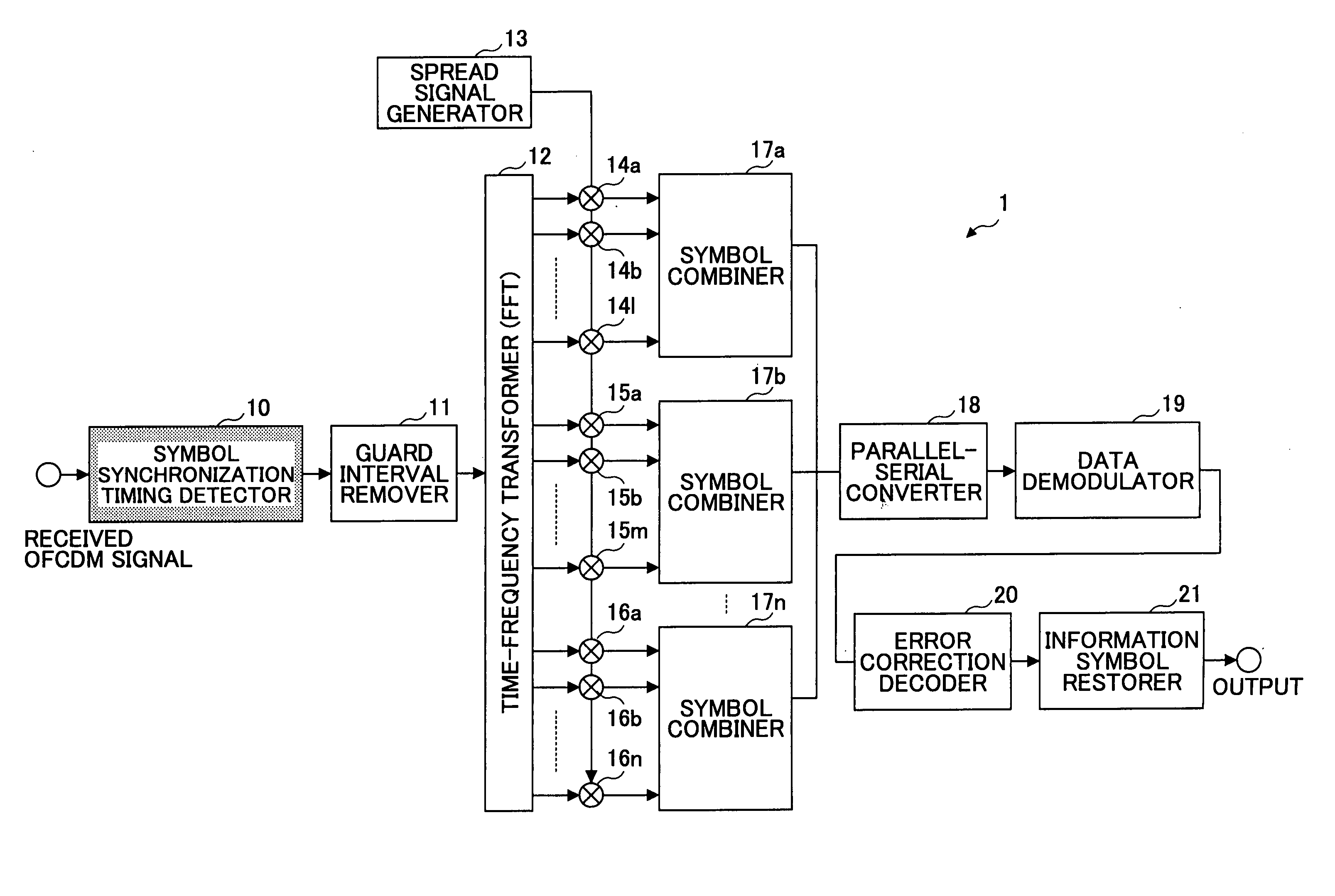
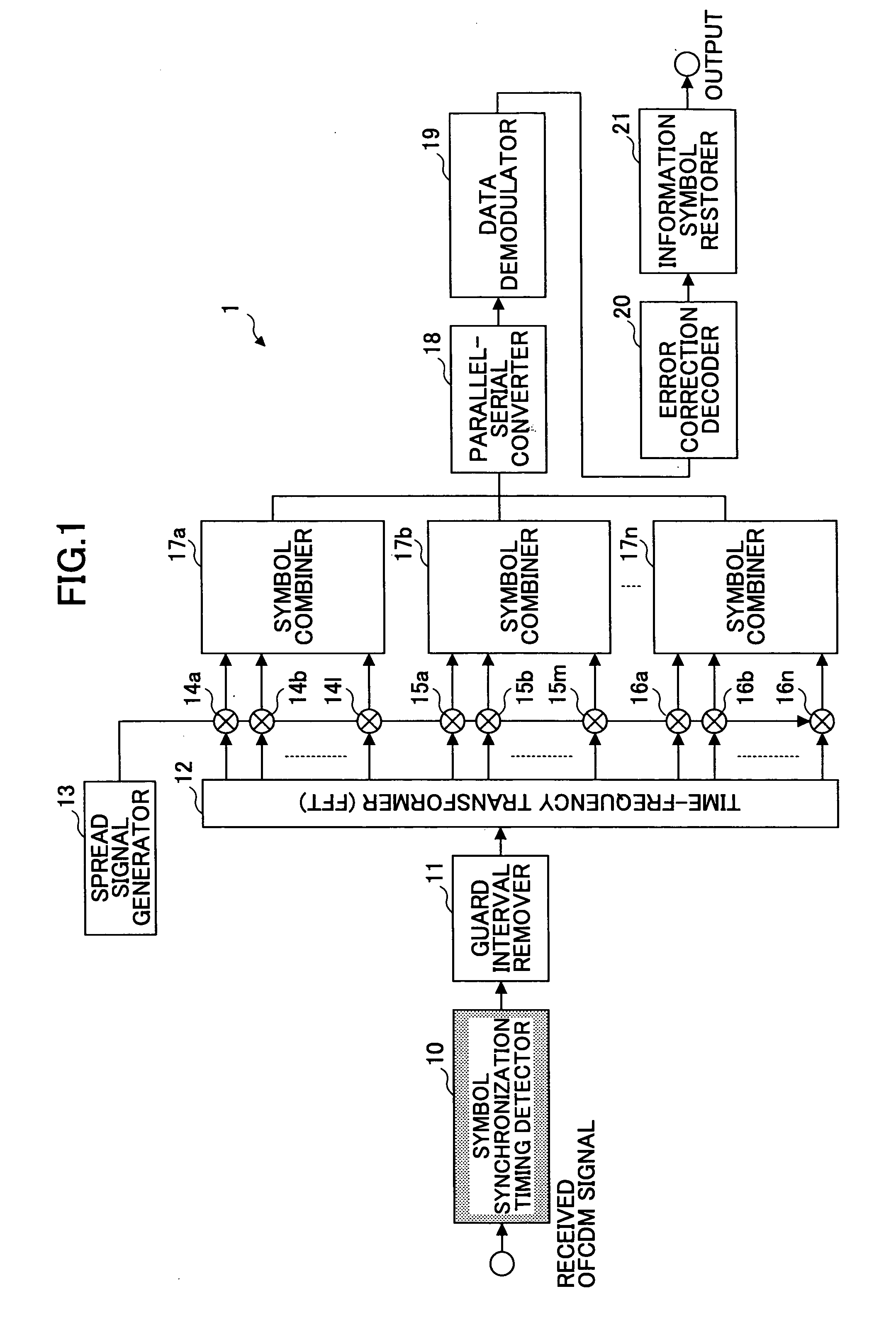
[0063]FIG. 1 is a block diagram showing a configuration of an OFCDM signal reception device, which adopts an OFCDM (Orthogonal Frequency and Code Division Multiplexing) transmission scheme, according to an embodiment of the present invention.

[0064] In the OFCDM transmission scheme, information symbols are duplicated and arranged in a time axis and a frequency axis; each of the duplicated information symbols is multiplied with a spread code in the time axis and frequency axis, and the thus obtained spread signals are transmitted by a number of symbols at different times and a number of sub-carriers having different frequencies.

[0065] The OFCDM transmission scheme is a typical multiplexing method employing a number of carriers in the down-link channel in a mobile communication system.

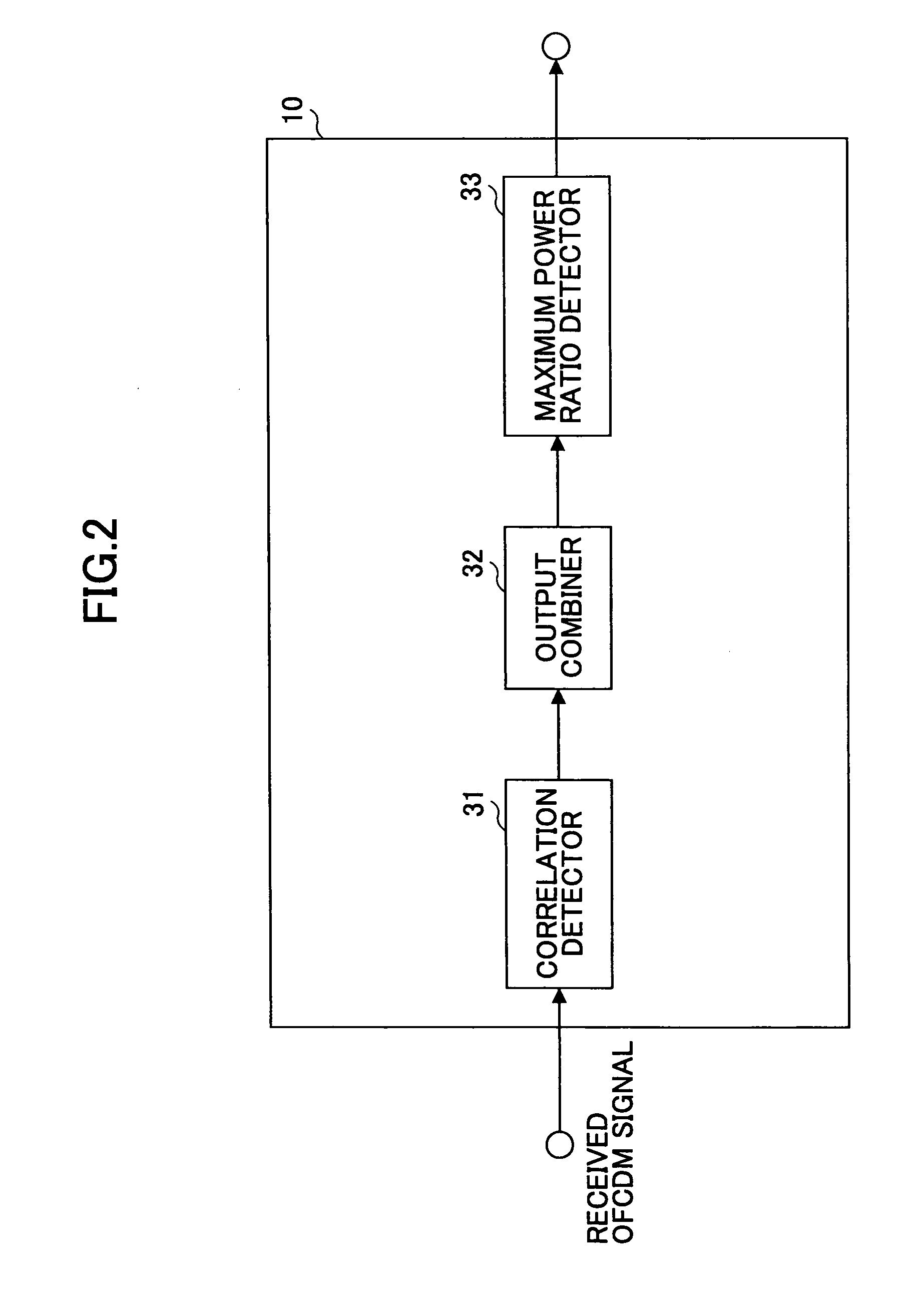
[0066] In FIG. 1, the OFCDM signal reception device 1 includes a symbol synchroni...


PUM


Abstract

A signal reception device is disclosed that is capable of detecting symbol synchronization timing with high precision in accordance with a condition of a propagation path even in an environment involving multi-path interference. The signal reception device adopts an OFCDM transmission scheme or a multi-carrier transmission scheme. The signal reception device includes a received signal information calculation unit to calculate received signal information representing a signal reception condition of a received signal; an output combination unit to combine correlation values in a predetermined section obtained by correlation detection based on the received signal information; and a symbol timing detection unit to detect a symbol synchronization timing based on the combined value.

Description

BACKGROUND OF THE INVENTION [0001] 1. Field of the Invention [0002] The present invention generally relates to a signal reception device and a method of detecting a timing of signal reception in a mobile communication system, and in particular, to a signal reception device and a method of signal reception timing detection employing an OFCDM (Orthogonal Frequency and Code Division Multiplexing) transmission scheme or a multi-carrier transmission scheme. [0003] 2. Description of the Related Art [0004] At the present time, study is being made of radio transmission schemes for the fourth generation mobile communication system aiming at higher speed and larger capacity than the third generation mobile communication system (W-CDMA). For example, a multi-carrier CDMA (Code Division Multiple Access) scheme, which involves multiplication of spread codes in a frequency axis, has tolerance for frequency-selectivity of propagation paths arising from existence of multiple paths, which causes a p...

Claims


Application Information

Patent Timeline
Patent Type & Authority Applications(United States)
IPC IPC(8): H04J99/00H04J11/00H04L5/02H04L27/26H04L27/28
CPCH04L5/026H04L27/2662H04L27/2695H04L27/2675H04L27/2678H04L27/2602H04B17/336H04L25/0224
Inventor NAGATA, SATOSHIMAEDA, NORIYUKIATARASHI, HIROYUKISAWAHASHI, MAMORU
Owner NTT DOCOMO INC
Why Eureka
Try Eureka