
Image signal processing method, image signal processing apparatus, and image signal processing program

a signal processing and image technology, applied in the field of image signal processing methods, image signal processing apparatuses, and image signal programs, can solve the problems of blurring of images, affecting the original frequency components of input images, and achieving no enhancement of the other parts at all, so as to relieve the blur caused by the change of frequency components, the effect of easy adjustmen

Inactive Publication Date: 2005-05-12
NTT DOCOMO INC
View PDF9 Cites 26 Cited by
  • Summary
  • Abstract
  • Description
  • Claims
  • Application Information

AI Technical Summary

Benefits of technology

The present invention provides an image signal processing method and apparatus that can reduce blur in images caused by coding distortion, edge enhancement, and resolution conversion. The method involves importing an image, performing a predetermined filtering process on the image to generate a filtered image, and performing a functional operation between some or all of the frequency components of the filtered image and the original image to generate frequency components of a function-operated image. These frequency components are then transformed into pixel values to improve the quality of the image. The invention can also adjust the amount of filtering based on the desired quality of the image. Overall, the invention helps to maintain the original details of the image while reducing blur and improving image quality.

Problems solved by technology

However, the use of the low-pass filter and the enhancement of edge part will result in also affecting the original frequency components of the input image.
The edge enhancement process is effective for edge part, but achieves no enhancement of the other part at all.
For this reason, the influence of the low-pass filter is left to cause a drawback of blur of an image.
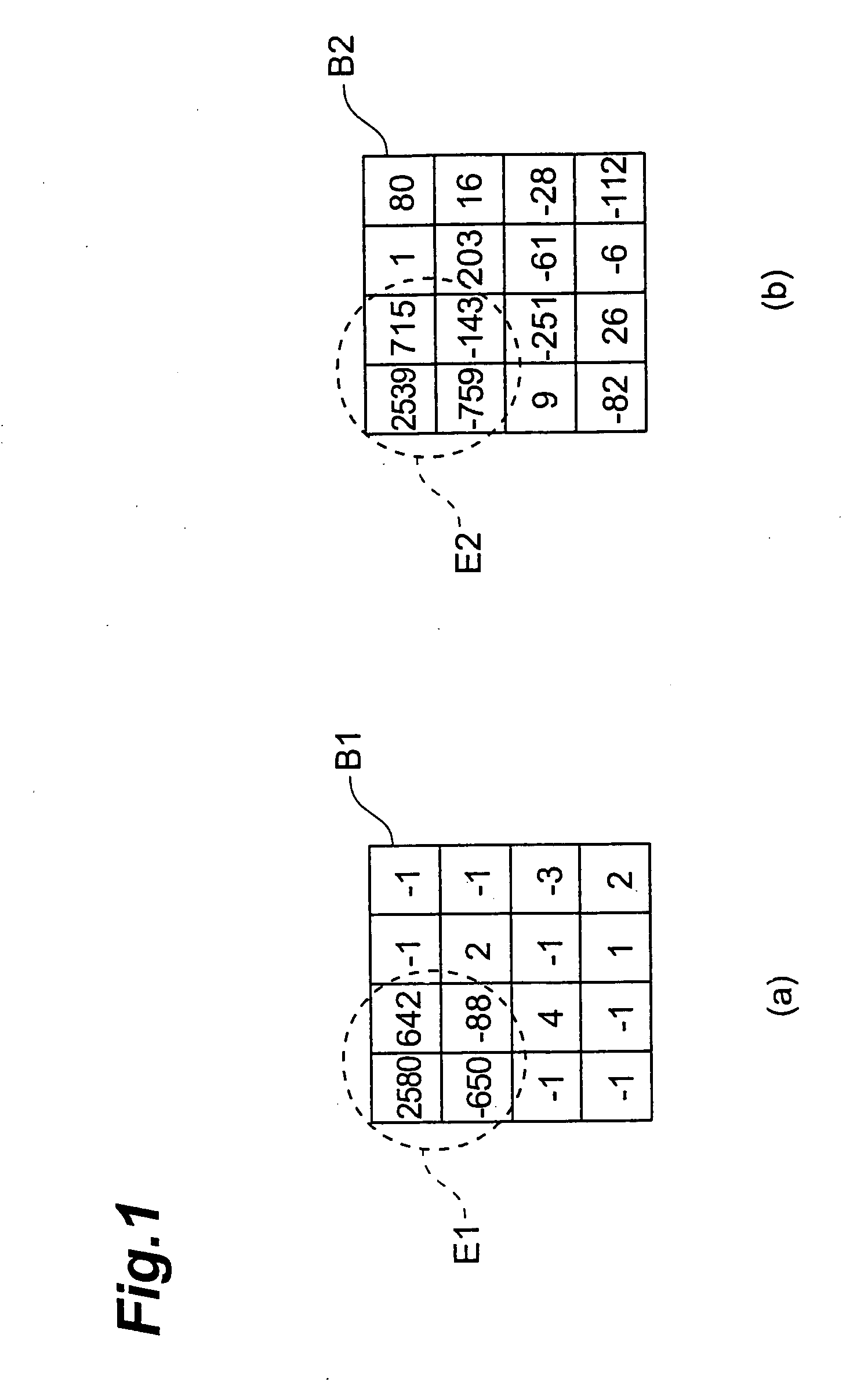
This change of frequency components leaves out details of the block to cause blur of the input image.
This problem also arises in conversion of resolution of an image, particularly, in upsampling of image size.

Method used


Image

  • Image signal processing method, image signal processing apparatus, and image signal processing program
  • Image signal processing method, image signal processing apparatus, and image signal processing program
  • Image signal processing method, image signal processing apparatus, and image signal processing program

Examples


first embodiment

[0032] The first embodiment of the present invention will be described below with reference to FIGS. 2 to 7.

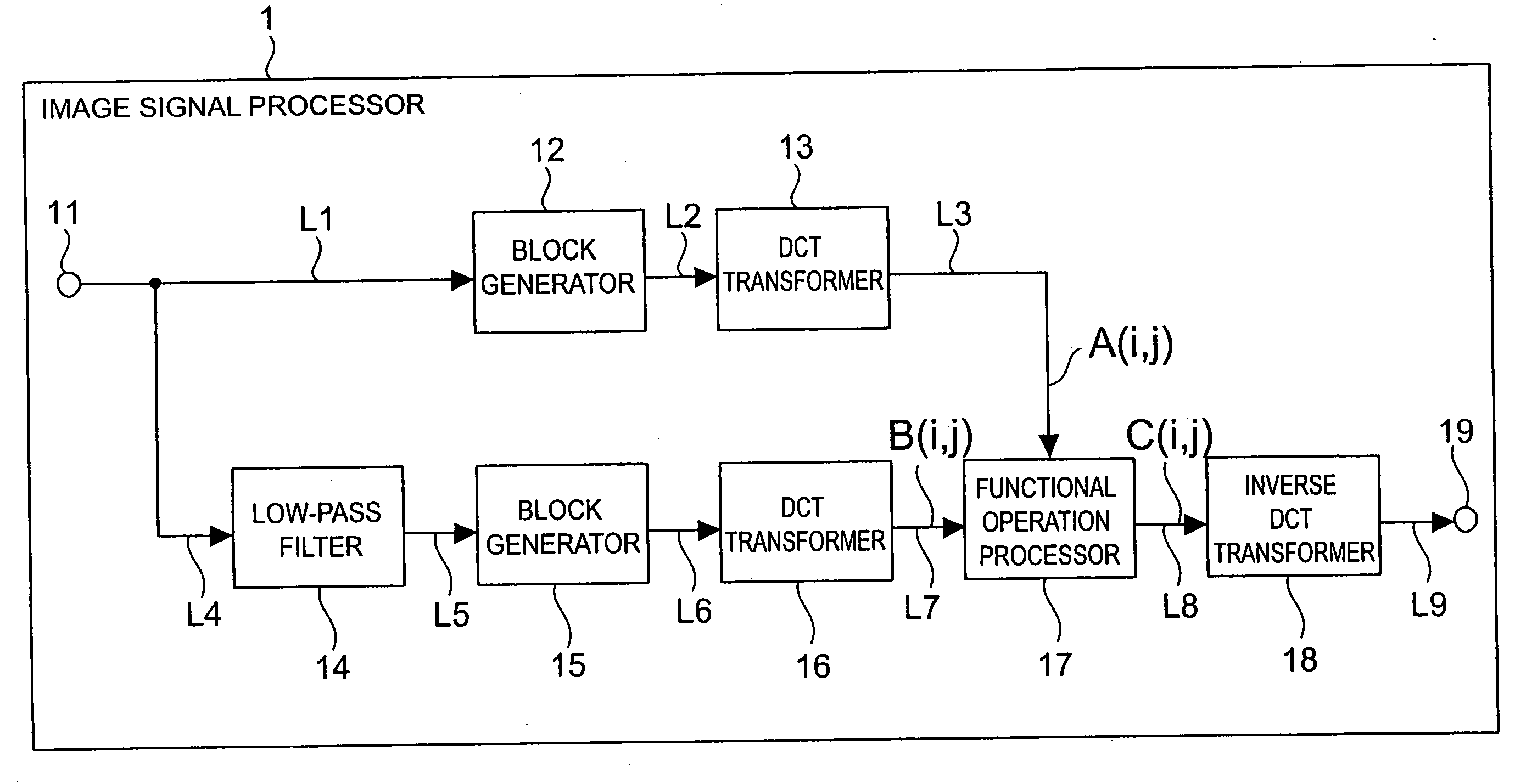
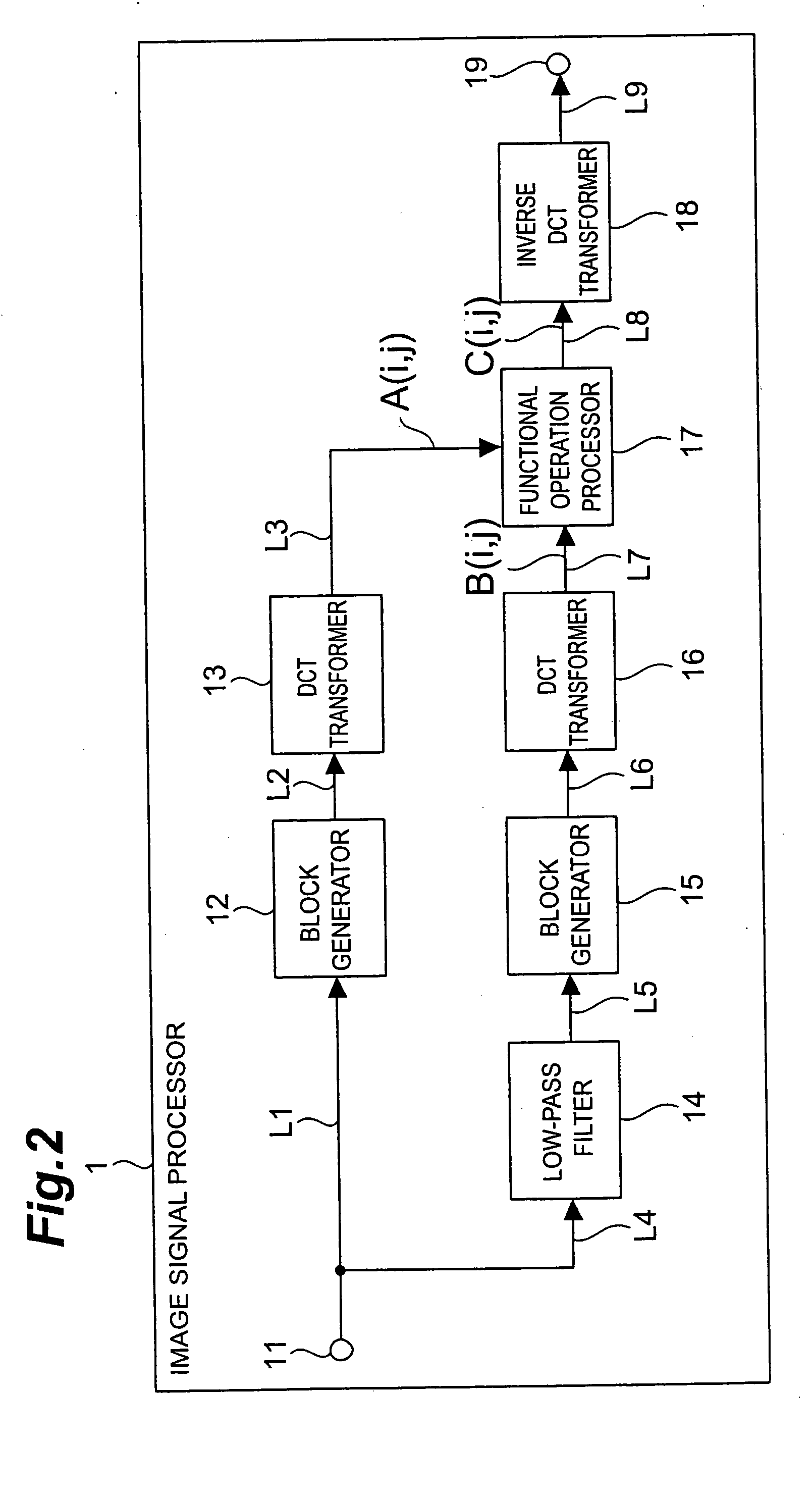
[0033] First, a configuration will be described. FIG. 2 is a block diagram showing a functional configuration of an image signal processing apparatus in the present embodiment. As shown in FIG. 2, the image signal processing apparatus 1 is comprised of an input terminal 11 (corresponding to the importing means), a block generator 12, a discrete cosine (DCT: Discrete Cosine Transform) transformer 13 (corresponding to the first acquiring means), a low-pass filter 14 (corresponding to the first generating means), a block generator 15, a DCT transformer 16 (corresponding to the second acquiring means), a functional operation processor 17 (corresponding to the second generating means), an inverse DCT transformer 18 (corresponding to the transforming means), and an output terminal 19.

[0034] An image from a decoder compatible with MPEG-4 AVC / H.264 is fed to the input terminal 11. T...

second embodiment

[0071] The first embodiment used the low-pass filter 14 (cf. FIG. 2), but an upsampling filter may replace it to convert a resolution (image size) of an input image from the input terminal.

[0072] Differences of the present embodiment from the first embodiment will be described below.

[0073]FIG. 10 is a block diagram showing a functional configuration of an image signal processing apparatus in the present embodiment. As shown in FIG. 10, the image signal processing apparatus 2 is comprised of an input terminal 21 (corresponding to the importing means), a block generator 22, a DCT transformer 23 (corresponding to the first acquiring means), an upsampling filter 24 (corresponding to the first generating means), a block generator 25, a DCT transformer 26 (corresponding to the second acquiring means), a functional operation processor 27 (corresponding to the second generating means), an inverse DCT transformer 28 (corresponding to the transforming means), and an output terminal 29.

[007...


PUM


Abstract

An image signal processing apparatus 1 has at least an input terminal 11, a DCT transformer 13, a low-pass filter 14, a DCT transformer 16, a functional operation processor 17, and an inverse DCT transformer 18. With input of an image at the input terminal 11, the DCT transformer 13 acquires frequency components of the input image. On the other hand, the low-pass filter 14 performs a filtering process on the input image from the input terminal 11 to generate a filtered image. The DCT transformer 16 acquires frequency components of this image. The functional operation processor 17 performs a functional operation between some of the frequency components of the images before and after the filtering to generate frequency components of a function-operated image. The inverse DCT transformer 18 transforms the frequency components into pixel values and outputs them.

Description

BACKGROUND OF THE INVENTION [0001] 1. Field of the Invention [0002] The present invention relates to an image signal processing method, an image signal processing apparatus, and an image signal program and, more particularly, to techniques of removing image distortion and enhancing sharpness of an image. [0003] 2. Related Background Art [0004] Conventionally, compression coding techniques are used for efficiently carrying out transmission and storage of data of still images and moving pictures. Among the compression coding techniques, typical systems are JPEG (Joint Photographic Experts Group) in the case of still images and MPEG (Moving Picture Experts Group) in the case of moving pictures. [0005] Compression coding of an image removes part of a signal, and thus a reproduced image suffers coding distortion such as the block boundary effect and ringing. Specifically, the quantization process for reduction of data volume removes high frequency components of an image signal. Particula...

Claims


Application Information

Patent Timeline
Patent Type & Authority Applications(United States)
IPC IPC(8): G06K9/40G06T5/00G06T5/20G06T5/10H04N1/387H04N1/409H04N5/208H04N5/21H04N5/46H04N19/00H04N19/117H04N19/134H04N19/157H04N19/159H04N19/176H04N19/44H04N19/59H04N19/625H04N19/86
CPCG06T5/10H04N5/208G06T5/003G06T2207/20052G06T2207/20192H04N19/176H04N19/527H04N19/117H04N19/14H04N19/18H04N19/48H04N19/80H04N19/61G06T5/73
Inventor BOON, CHOONG SENGTAN, THIOW KENG
Owner NTT DOCOMO INC
Learn More