Active metal fuel cells

a fuel cell and active metal technology, applied in the field of active metal electrochemical devices, can solve the problems of not being able to isolate the highly reactive anode alkali metal fuel from the cathode oxidant, and not being able to leverage the advantages of lithium and other alkali or other active metals in the fuel cell, so as to improve the energy density and fuel efficiency of the system.

Inactive Publication Date: 2005-05-12
POLYPLUS BATTERY CO INC
View PDF99 Cites 88 Cited by
  • Summary
  • Abstract
  • Description
  • Claims
  • Application Information

AI Technical Summary

Benefits of technology

The patent text describes a system that combines two types of fuel cells to capture and use the hydrogen released during the process. This improves the energy density and fuel efficiency of the system.

Problems solved by technology

This patent discusses how new technology allows us to use active metals like lithium as fuel cell electrodes. These metals have many benefits but they cannot be easily isolated because they react too quickly with other substances. The technical problem this patent solves is finding ways to prevent the reaction between the active metal and another material while still allowing the metal to function properly in the fuel cell.

Method used


Image

  • Active metal fuel cells
  • Active metal fuel cells
  • Active metal fuel cells

Examples


Embodiment Construction

[0020] Reference will now be made in detail to specific embodiments of the invention. Examples of the specific embodiments are illustrated in the accompanying drawings. While the invention will be described in conjunction with these specific embodiments, it will be understood that it is not intended to limit the invention to such specific embodiments. On the contrary, it is intended to cover alternatives, modifications, and equivalents as may be included within the spirit and scope of the invention as defined by the appended claims. In the following description, numerous specific details are set forth in order to provide a thorough understanding of the present invention. The present invention may be practiced without some or all of these specific details. In other instances, well known process operations have not been described in detail in order not to unnecessarily obscure the present invention.

[0021] When used in combination with “comprising,”“a method comprising,”“a device comp...


PUM


Abstract

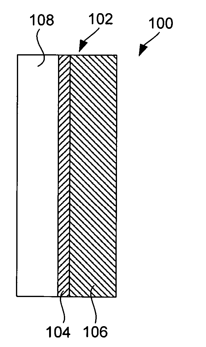
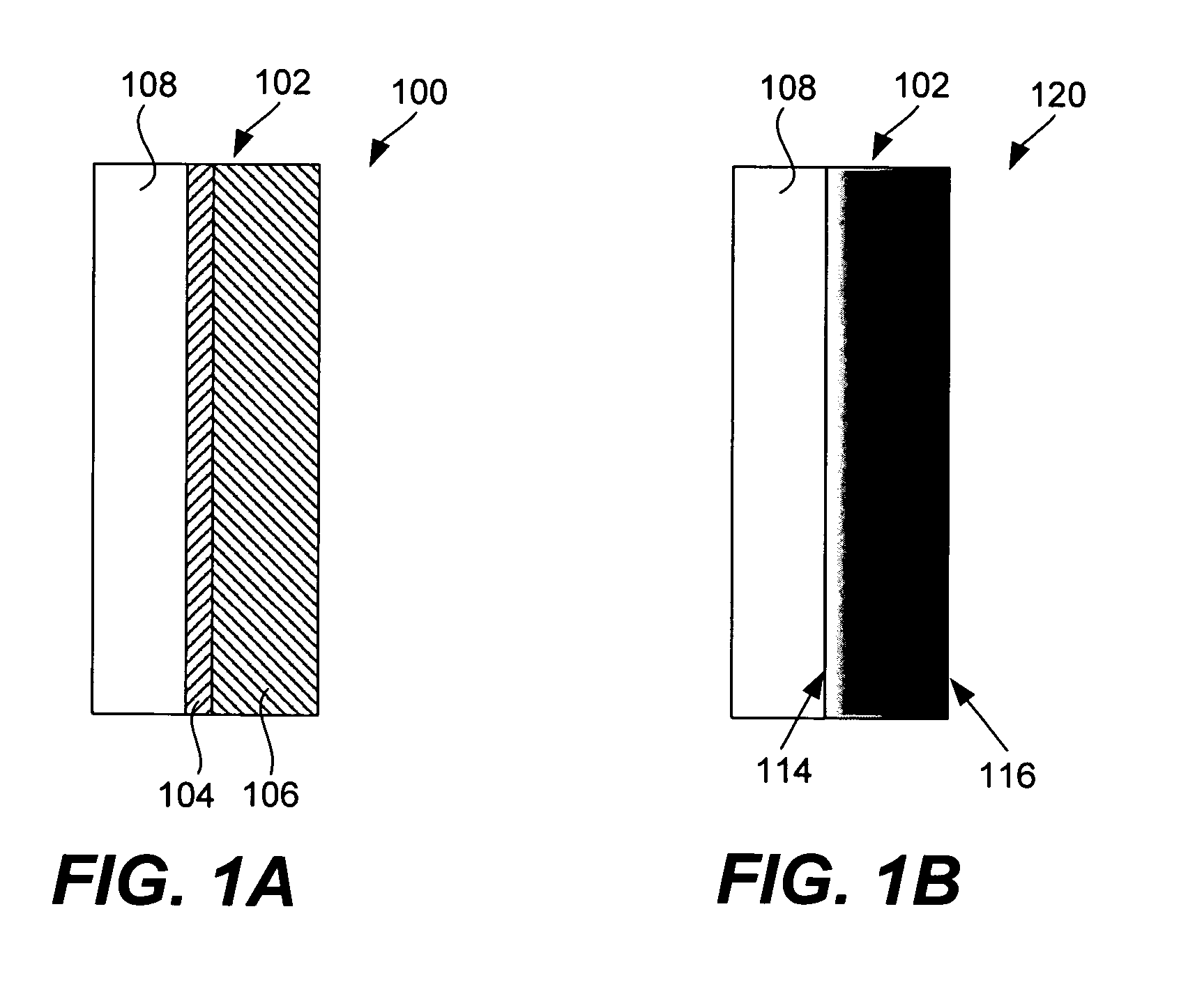
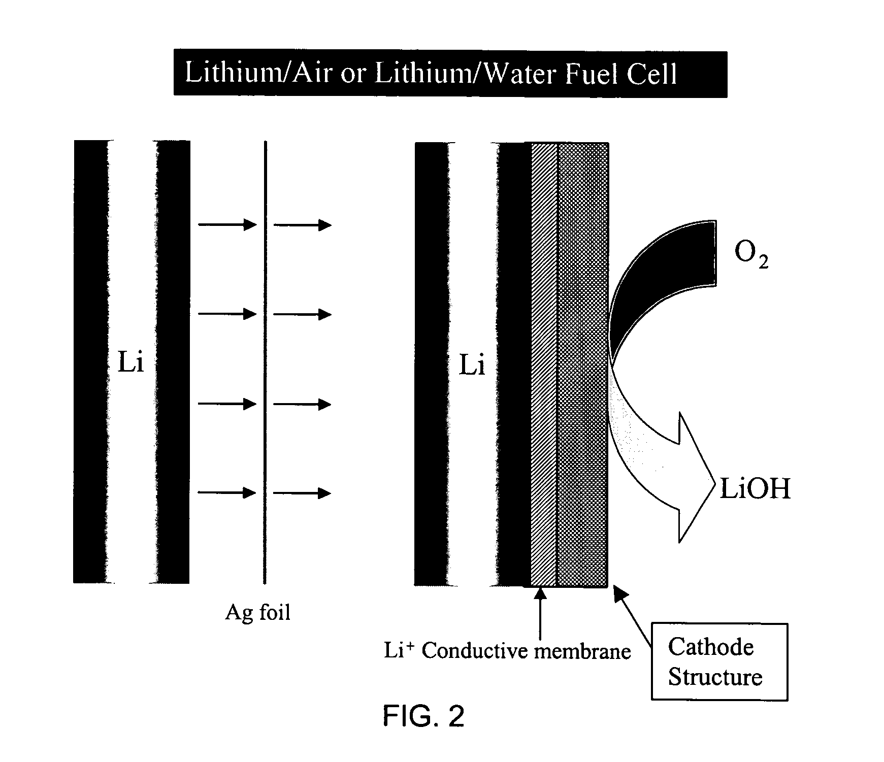
Active metal fuel cells are provided. An active metal fuel cell has a renewable active metal (e.g., lithium) anode and a cathode structure that includes an electronically conductive component (e.g., a porous metal or alloy), an ionically conductive component (e.g., an electrolyte), and a fluid oxidant (e.g., air, water or a peroxide or other aqueous solution). The pairing of an active metal anode with a cathode oxidant in a fuel cell is enabled by an ionically conductive protective membrane on the surface of the anode facing the cathode.

Description


Claims


Application Information

Patent Timeline
Owner POLYPLUS BATTERY CO INC
Why Eureka
Try Eureka