Stretchable prosthesis fenestration

a prosthesis and fenestration technology, applied in the field of medical devices, can solve the problems of frequent blockage of the flow of blood to the side branch vessels, damage to the perfused tissue, and deficiency in the connection between the balloon expanded stent and the stent graft at the fenestration, and achieve the effect of never completely snug or tigh

Active Publication Date: 2005-05-12
COOK MEDICAL TECH LLC
View PDF22 Cites 205 Cited by
  • Summary
  • Abstract
  • Description
  • Claims
  • Application Information

AI Technical Summary

Benefits of technology

[0007] The foregoing problems are solved and a technical advance is achieved in an illustrative embodiment of a stretchable prosthesis fenestration including a variable size fenestration in the stent graft of the present invention. This invention provides a variable size fenestration or hole in the stent, graft or stent graft that is stretchable or elastic. By being stretchable, a balloon expandable stent can be advantageously expanded beyond the diameter of the fenestration without damaging the stent, graft or stent graft and will recoil along with the balloon expanded stent and maintain a close, snug fit to it. An expandable frame is disposed at least partially about the fenestration and at least partially controls the variable size of the fenestration to advantageously accommodate a close or snug fit with another prosthesis such as a stent, graft or stent graft positioned therethrough.

Problems solved by technology

However, these stent grafts frequently block the flow of blood to the side branch vessels that carry blood to other organs and anatomy.
The occlusion of the side branch vessels can result in damage to the tissue perfused by the blood flow from the side branch vessel.
Patients receiving stent grafts usually do so because they are too weak or sick to endure surgery.
While this balloon stenting through a fenestration process is fairly effective, it is deficient in that the connection between the balloon expanded stent and the stent graft at the fenestration is never completely snug or tight.
As a result, leaks often occur between the stent graft and aortic wall.
As a result, the fit between the balloon expandable stent and the stent graft fenestration is never truly tight.
Before endothelialization occurs, the patient is still at risk of a ruptured aneurysm.
In some cases, where the gap between the stent graft and aortic wall is large, a seal at the fenestration may never occur, leaving the patient with minimal or no protection from a ruptured aneurysm.

Method used


Image

  • Stretchable prosthesis fenestration
  • Stretchable prosthesis fenestration
  • Stretchable prosthesis fenestration

Examples


Embodiment Construction

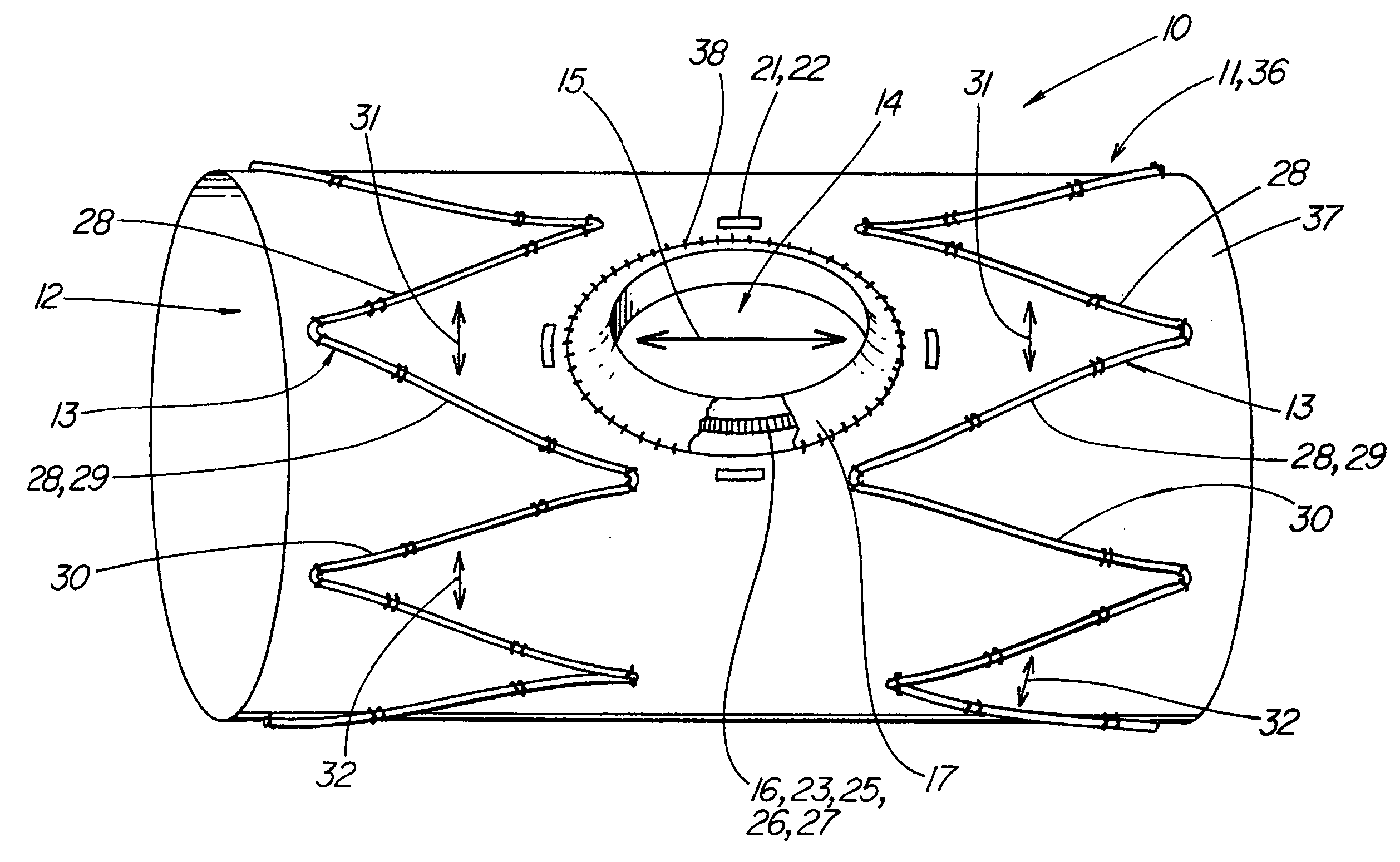
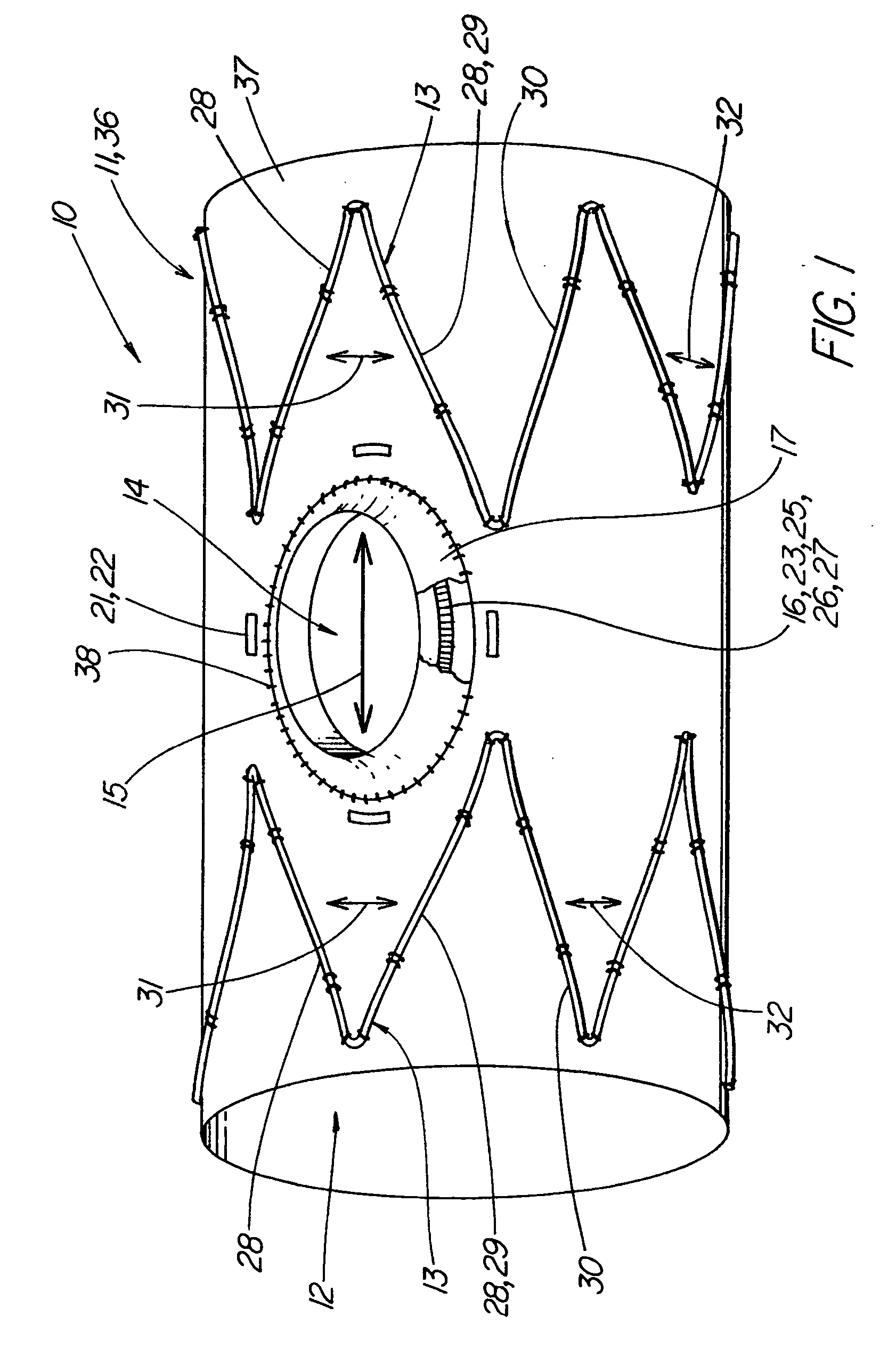
[0014]FIG. 1 depicts a pictorial view of a segment of an illustrative prosthesis 10 such as a stent graft of the present invention in which a variable size fenestration 14 is disposed in tubular graft 11, 36. Biocompatible tubular graft 11 or elongated tubular member 36 of graft material 37 includes a lumen 12 extending longitudinally therethrough.

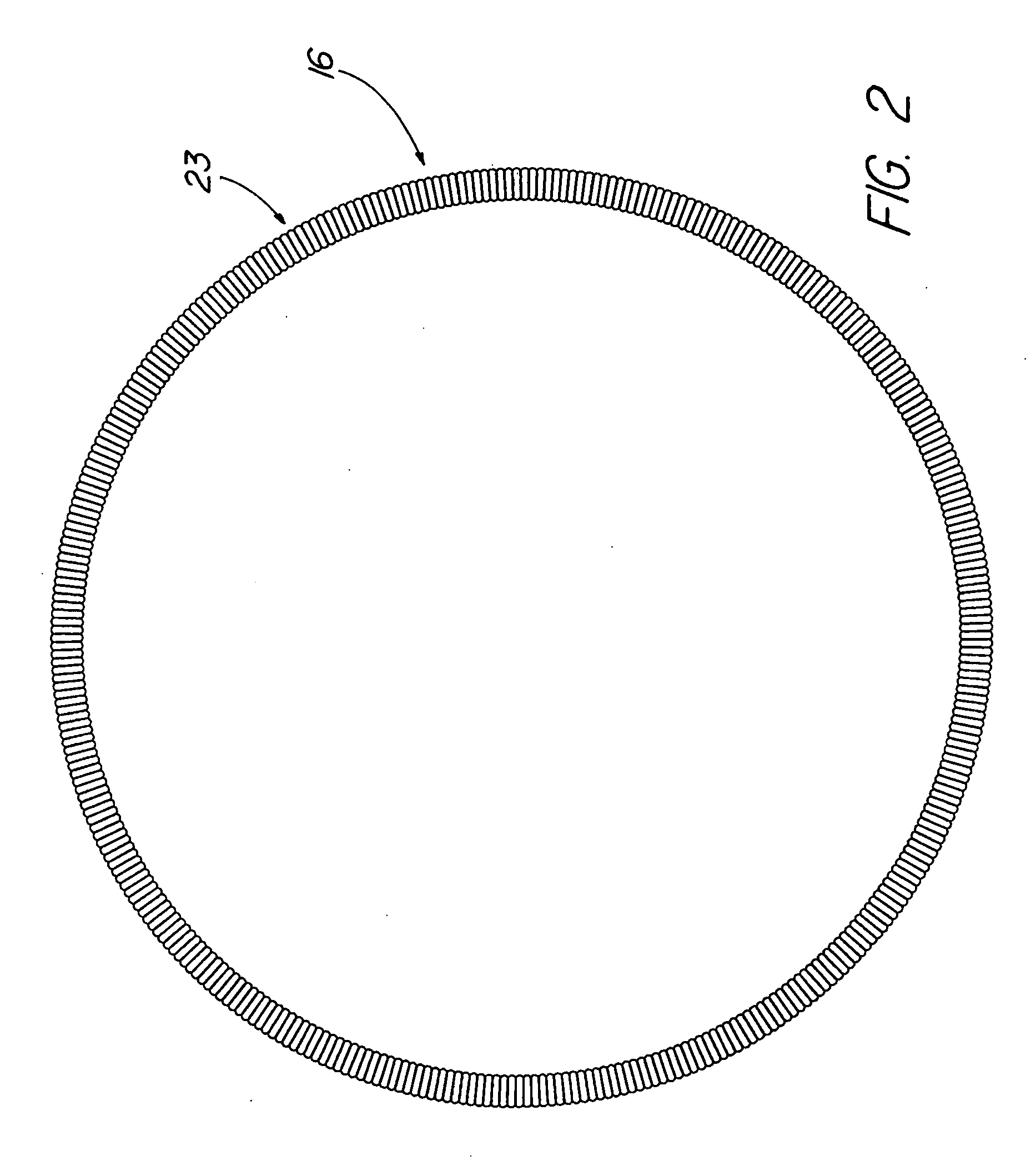
[0015] The fenestration 14 can be made by first cutting a round hole in the graft material 37 that is considerably smaller than the desired finished hole. An expandable frame 16 such as a stretchable coil loop 23 as in FIG. 2 is laid on the graft material, around the hole, then the graft material is everted through the coil loop and out over the loop back onto the graft material. The edge can then be sutured or sewn to the graft material using well-known sutures 38 and capturing the coil loop at the resulting hole or fenestration. The result is prosthesis 10, tubular graft 11, or elongated tubular member 36 depicted in FIG. 1. A tubular g...


PUM


Abstract

A prosthesis (10) having a variable size or stretchable fenestration (14) in the graft material (37) of a biocompatible tubular graft (11). An expandable frame (16) is disposed about the fenestration, and a portion (17) of the graft material about the fenestration is folded back over the frame to cover the frame. Additional grafts or prosthesis of varying size can be inserted through the frame and fenestration with the stretched frame and folded portion compressing on the inserted graft forming a seal therewith.

Description

CROSS-REFERENCE TO RELATED APPLICATIONS [0001] This application claims priority of provisional application Ser. No. 60 / 510,243, filed Oct. 10, 1003.TECHNICAL FIELD [0002] This invention is related to medical devices and, in particular, to a prosthesis having a fenestration. BACKGROUND OF THE INVENTION [0003] Prostheses such as stent grafts as used for stenting or repairing aneurysms as in the abdominal or thoracic aorta are usually fairly effective at excluding the aneurysm from exposure to blood pressure and therefore protect the patient from the dangers of aneurysm rupture. However, these stent grafts frequently block the flow of blood to the side branch vessels that carry blood to other organs and anatomy. The occlusion of the side branch vessels can result in damage to the tissue perfused by the blood flow from the side branch vessel. [0004] Attempts to deal with these occlusions have been such things as by-pass vessels placed surgically to restore blood flow from a region of th...

Claims


Application Information

Patent Timeline
Patent Type & Authority Applications(United States)
IPC IPC(8): A61F2/06A61F2/82
CPCA61F2/07A61F2002/061A61F2/89A61F2002/821A61F2002/075
Inventor OSBORNE, THOMAS A.
Owner COOK MEDICAL TECH LLC
Why Eureka
Try Eureka