Shims, particularly for laterally placed artificial disc replacements (ADRS)

Inactive Publication Date: 2005-05-12
FERREE BRET A
View PDF13 Cites 19 Cited by
  • Summary
  • Abstract
  • Description
  • Claims
  • Application Information

AI Technical Summary

Benefits of technology

[0008] To address problems associated with the existing art, this invention uses shims between the lateral edge of the vertebra and the plate of a laterally placed ADR. The shims assist in the placement of the ADR center of rotation (COR) in the mid-sagittal line. The shims also customize the fit between the lateral surface of the vertebral body and the plate portion of the ADR, since the lateral surface of a vertebral body often has a central concavity. The modular shims also help reduce ADR inventory by facilitating customization of standard ADRs.

Problems solved by technology

Motion across arthritic facet joints could lead to pain following ADR.
In fact, ADRs of this kind may not, by themselves, provide sufficient distraction across the disc space.
Replicating the movements of the natural disc also decreases the risk of separation of the ADR from the vertebrae above and below the ADR.

Method used


Image

  • Shims, particularly for laterally placed artificial disc replacements (ADRS)
  • Shims, particularly for laterally placed artificial disc replacements (ADRS)
  • Shims, particularly for laterally placed artificial disc replacements (ADRS)

Examples


Embodiment Construction

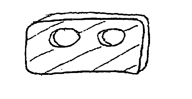
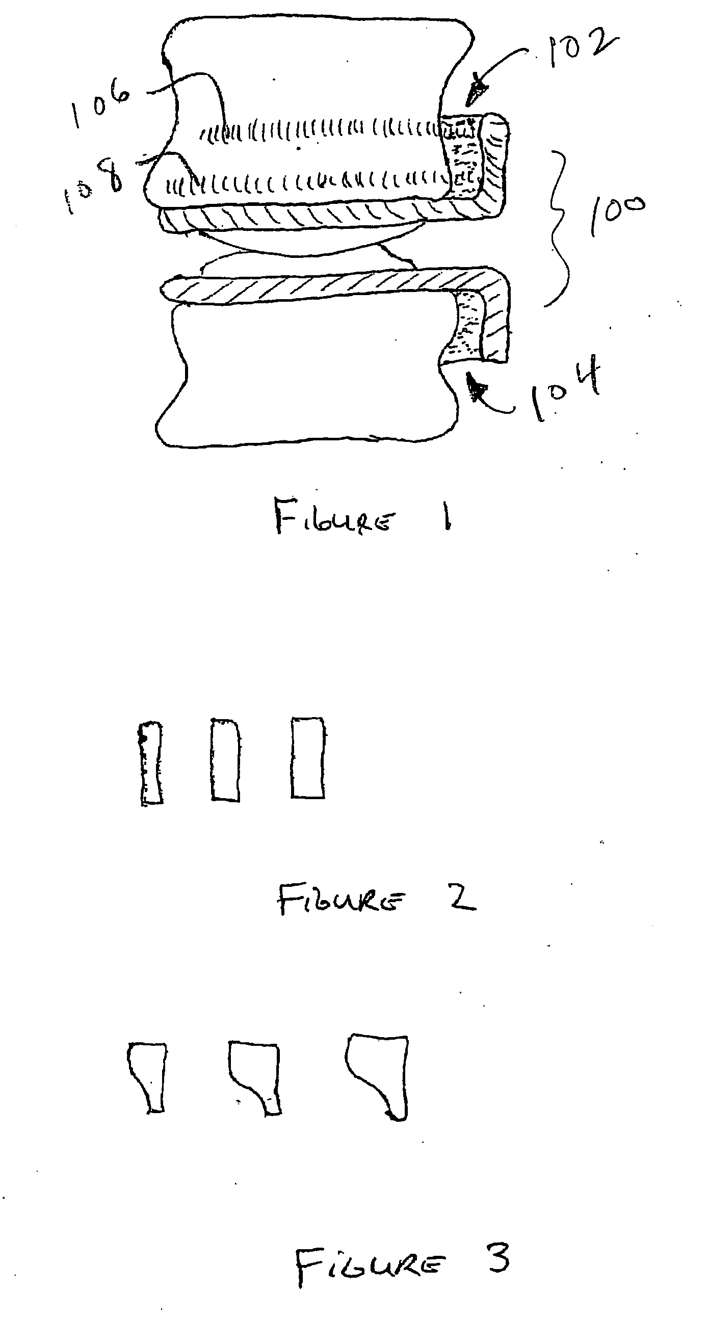
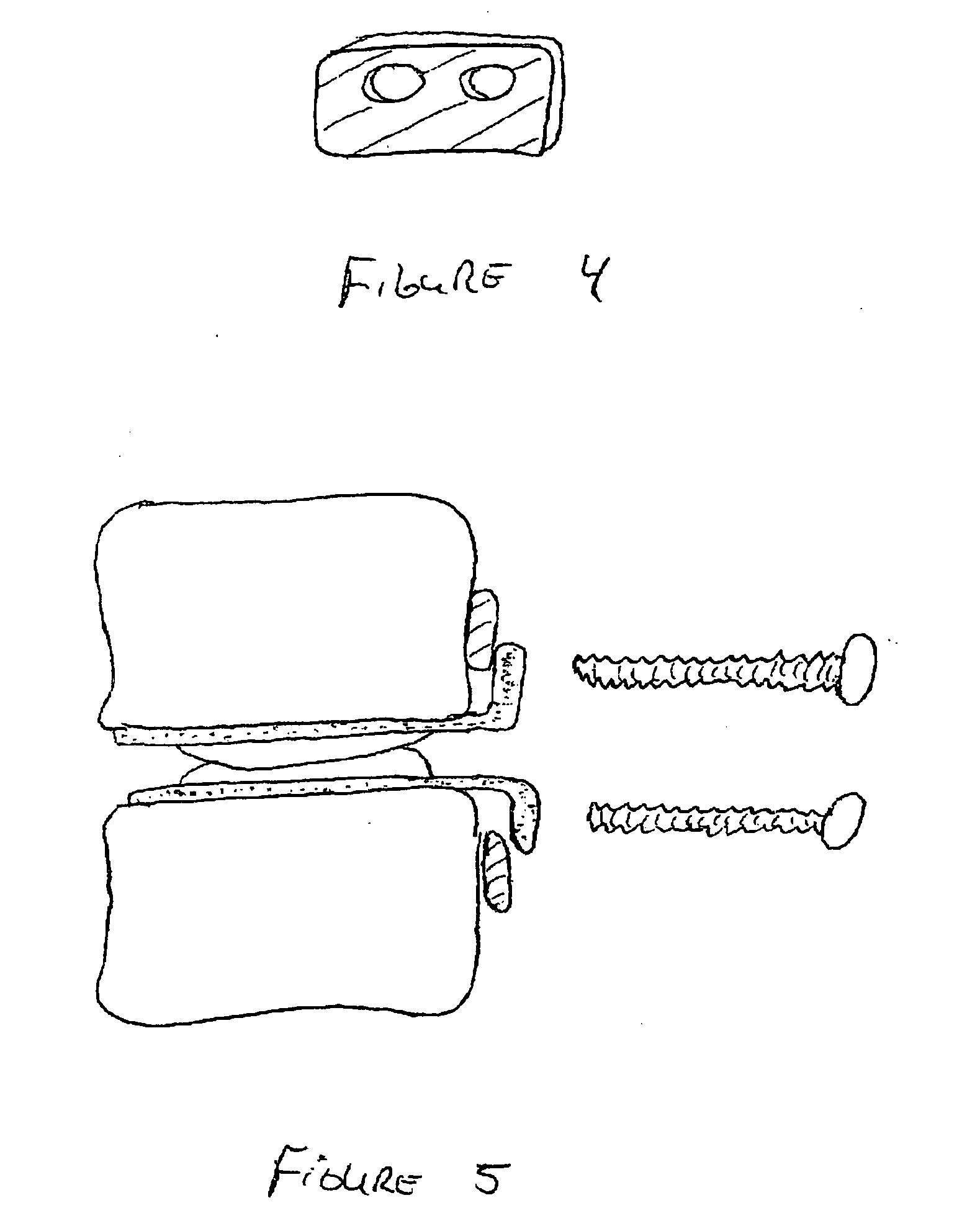
[0015]FIG. 1 is a view of the anterior surface of the spine, a laterally placed ADR 100, and shims 102, 104. The trajectory of the screws 106, 108 is illustrated in the upper vertebra. Note that although shims are shown in conjunction with both the upper and lower vertebra, only a single shim may be indicated. FIG. 2 is a view of the front of shims in various sizes. FIG. 3 is a view of the front shims in various shapes. FIG. 4 is an anterior view of the shim drawn in FIG. 2.

[0016]FIG. 5 is an anterior view of the spine and an exploded anterior view of the invention. Although the drawings illustrate the use of screws to hold the shims between the ADR and the vertebrae, the invention may include other fastening mechanisms to hold the shims between the ADR and the vertebrae. Alternative embodiments may include the use of shims or ADR components with spring properties, shape-memory properties, plastic deformation, etc. The shims may also be placed between a plate-like component of an A...


PUM


Abstract

Shims are placed between the lateral edge of the vertebra and the plate of a laterally placed ADR. The shims assist in the placement of the ADR center of rotation (COR) in the mid-sagittal line. The shims also customize the fit between the lateral surface of the vertebral body and the plate portion of the ADR, since the lateral surface of a vertebral body often has a central concavity. The modular shims also help reduce ADR inventory by facilitating customization of standard ADRs.

Description

REFERENCE TO RELATED APPLICATIONS [0001] This application claims priority from U.S. Provisional Patent Application Ser. No. 60 / 519,372, filed Nov. 12, 2003, the entire content of which are incorporated herein by reference.FIELD OF THE INVENTION [0002] This invention relates generally to artificial disc replacements (ADRs) and, in particular, to shims applicable to laterally placed ADRs. BACKGROUND OF THE INVENTION [0003] Many spinal conditions, including degenerative disc disease, can be treated by spinal fusion or through artificial disc replacement (ADR). ADR has several advantages over spinal fusion. The most important advantage of ADR is the preservation of spinal motion. Spinal fusion eliminates motion across the fused segments of the spine. Consequently, the discs adjacent to the fused level are subjected to increased stress. The increased stress increases the changes of future surgery to treat the degeneration of the discs adjacent to the fusion. However, motion through an AD...

Claims


Application Information

Patent Timeline
IPC IPC(8): A61B17/86A61F2/00A61F2/30A61F2/44
CPCA61B17/86A61F2/30734A61F2/4425A61F2002/30092A61F2002/30153A61F2002/30578A61F2310/00179A61F2002/30736A61F2002/30785A61F2210/0014A61F2230/0019A61F2310/00023A61F2310/00029A61F2002/30616
Inventor FERREE, BRET A.
Owner FERREE BRET A
Why Eureka
Try Eureka